
Sealing jaw

a sealing seam and jaw technology, applied in the field of sealing jaws, can solve the problems of faulty right-angle sealing seams that are usually not noticed, bacteria present in the environment pass through faulty right-angle sealing seams into the product, and achieve the effect of reliable and durable seams

Inactive Publication Date: 2008-03-25
TETRA LAVAL HLDG & FINANCE SA
View PDF16 Cites 10 Cited by
  • Summary
  • Abstract
  • Description
  • Claims
  • Application Information

AI Technical Summary

Benefits of technology

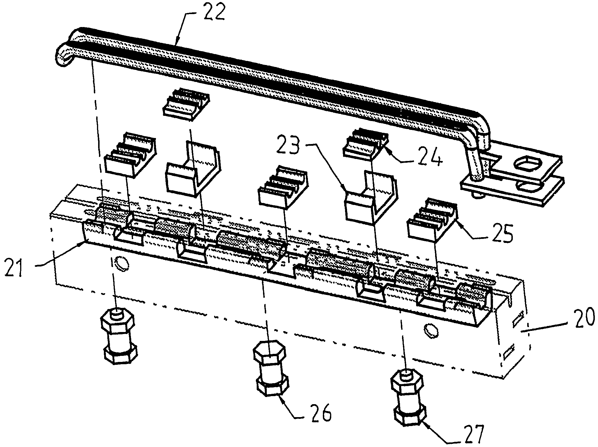
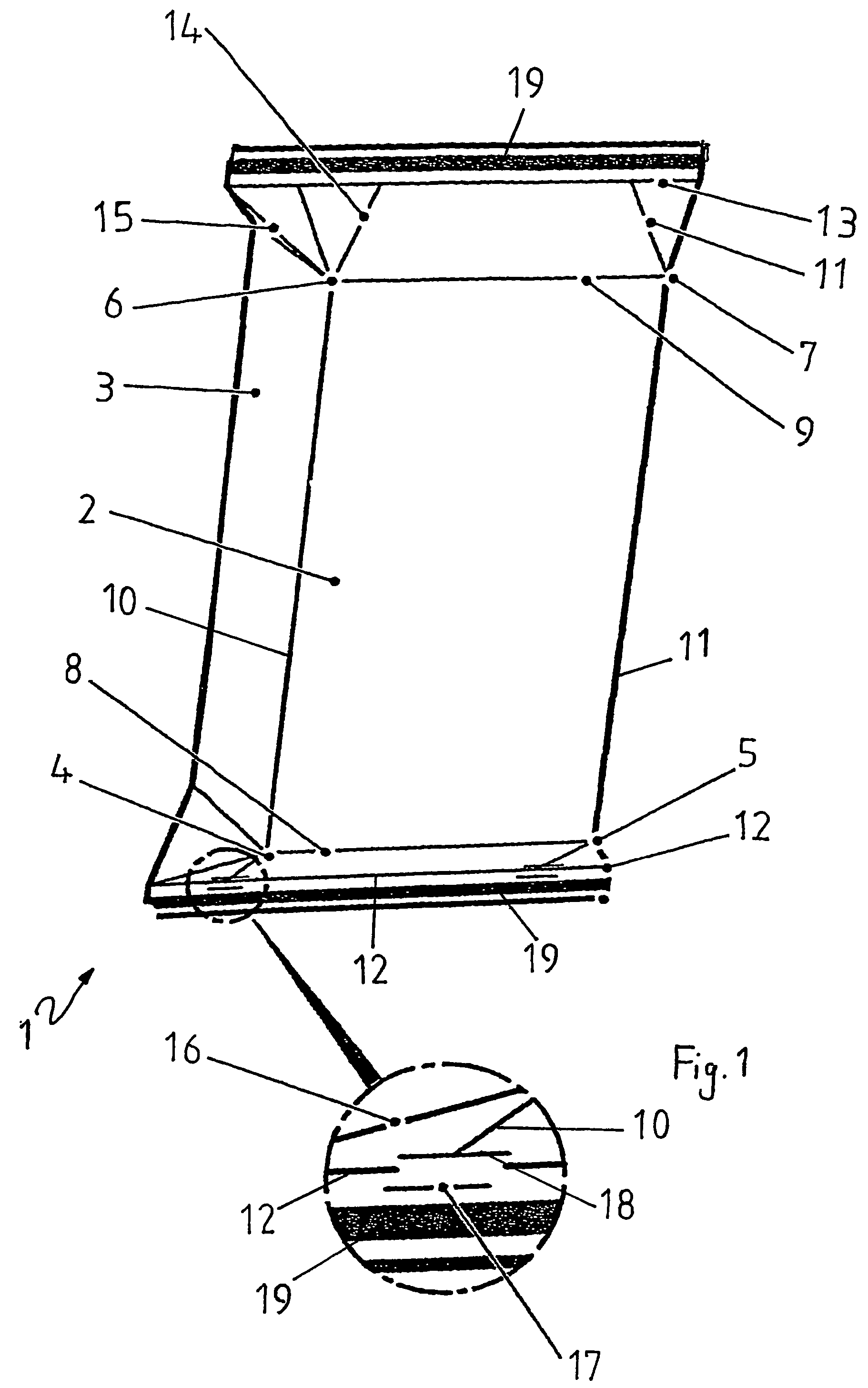
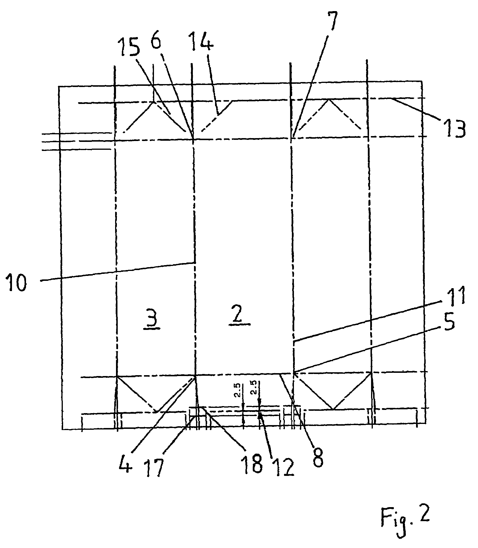
The present invention provides a sealing jaw that can produce a durable sealing seam even when solid components are trapped between the jaws. The sealing jaw has a sealing surface that comes into contact with the heat-sealable material and a rod or bar-shaped heating device to heat up the material. An additional pressure element is provided on the sealing surface, which helps to divide solid components and ensures a reliable and durable seam even when there are solids present in the sealing seam.

Problems solved by technology

This can lead to the right-angle sealing seam being less durable, or in the worst case even leaking from the outset.
Such a faulty right-angle sealing seam is usually not noticed immediately during the packaging process, however.
Nevertheless, bacteria present in the environment go through the faulty right-angle sealing seam into the product.
This can lead to fermentation and decay processes in food products, whereby the pressure within the package significantly increases and sooner or later the right-angle sealing seam bursts.
Even when this affects only a proportion of less than 0.1% of packages using the conventional sealing procedure, a defective right-angle sealing seam can have considerable disadvantageous consequences, in particular, when as is often the case the completed packages are placed on pallets in large numbers.
If a right-angle sealing seam is leaking, the contents of the faulty package leak over all the packages lying below it, so often even the undamaged packaged are virtually unsaleable because of their soiled outsides.

Method used


Image

  • Sealing jaw
  • Sealing jaw
  • Sealing jaw

Examples


Embodiment Construction

[0026]It has been shown that the pressure element is advantageously also rod or bar-shaped and is arranged substantially parallel to the heating device. This results in strengthening over a whole section of the sealing seam, whereby the leakage rate can be further reduced.

[0027]In numerous tests, it has been established that preferably the heating device and the pressure element are distanced apart from one another by at least 0.1 mm, preferably between 0.25 mm and 3 mm, particularly preferably between 0.5 mm and 1.5 mm.

[0028]The heating device can be configured, in principle, in many different ways. It can thus be composed of a thin wire to which, if necessary, a direct current can be applied in order to briefly heat the wire to a high temperature. It has been shown, however, that when packaging material with an electrically conductive layer is used, it is particularly advantageous when the heating device is an inductor. In this case, a high voltage is applied to the inductor so th...


PUM

PropertyMeasurementUnit
lengthaaaaaaaaaa
lengthaaaaaaaaaa
lengthaaaaaaaaaa

Abstract

A sealing jaw for manufacturing a sealing seam in a heat-sealable packaging material. The invention furthermore relates to an induction sealing device with a sealing jaw and to a packaging machine with induction sealing device. In order to provide a sealing jaw with which a sealed and durable sealing seam can be produced, even when solid components of the in-filled product are trapped between the jaws that have to be moved towards one another, a sealing jaw is proposed with means of a sealing jaw with a sealing surface that is provided in order to come into contact with the heat-sealable material, and a rod or bar-shaped heating device that is provided in order to heat up the heat-sealable material, wherein a pressure element is provided on the sealing surface, projecting above said sealing surface, and distanced from the heating device.

Description

BACKGROUND OF THE INVENTION[0001]The present invention relates to a sealing jaw for manufacturing a sealing seam in a heat-sealable packaging material. The invention furthermore relates to an induction sealing device with a sealing jaw and to a packaging machine with induction sealing device.[0002]Many flowable food products such as, for example, fruit juice, pasteurised or UHT milk, wine, tomato sauce and so forth are purchased in packages that are manufactured from sterilised packaging material.[0003]Cuboidal milk packages are known that are formed by folding and sealing laminated packaging material with a multi-layered structure that has a fibrous layer, for example, paper, that is covered on both sides with layers of heat-sealable plastics material, for example, polyethylene. In many applications, in particular in the case of sterile packages of products with very long shelf-life such as, for example, orange juice or tomato sauce, a packaging material is generally used that has ...

Claims


Application Information

Patent Timeline
Patent Type & Authority Patents(United States)
IPC IPC(8): H05B6/10A01J21/00B29C65/02B65B51/22
CPCB29C65/3656B29C65/368B29C66/232B29C66/72321B29C66/8167B29C66/8491B65B51/227B29C65/3668B29C66/1122B29C66/4312B29C66/81427B29C66/81429B29C66/81431B29C65/745B29C66/81457B29K2023/06B29K2305/02B29K2995/0069B29L2009/003B29L2031/7128B29C66/832B29C66/3472B29C66/8122B29C66/71B29L2031/7166B29C66/73921B29C66/7373B29C66/3462B29K2909/02B29K2871/00B65B51/22B65B51/10
Inventor KUPFER, REINHARDPALMQVIST, ROLAND
Owner TETRA LAVAL HLDG & FINANCE SA
Learn More