
Method and arrangement of rotating magnetically inducible particles

a magnetic inducible particle and arrangement technology, applied in the direction of mixing, mixing, chemistry apparatus and processes, etc., can solve the problems of large area limitation of the mixing effect of the conventional helmholtz coil-based system, relative complexity of such devices, and the inability to achieve the effect of efficient mixing action

Inactive Publication Date: 2008-03-18
THE ARIZONA BOARD OF REGENTS ON BEHALF OF THE UNIV OF ARIZONA
View PDF15 Cites 5 Cited by
  • Summary
  • Abstract
  • Description
  • Claims
  • Application Information

AI Technical Summary

Benefits of technology

The multidirectional magnetic field enables more efficient mixing by allowing each particle chain to span a larger volume, particularly beneficial for low-concentration suspensions, achieving a three-dimensional mixing effect throughout the fluid.

Problems solved by technology

There are certain disadvantages to magnetic mixing devices that employ the above-described Helmholtz coil arrangement.
One such disadvantage is the relative complexity of such devices, since the proper operation of the Hehnholtz coils requires the use of function generators, power amplifiers and cooling systems, among other things.
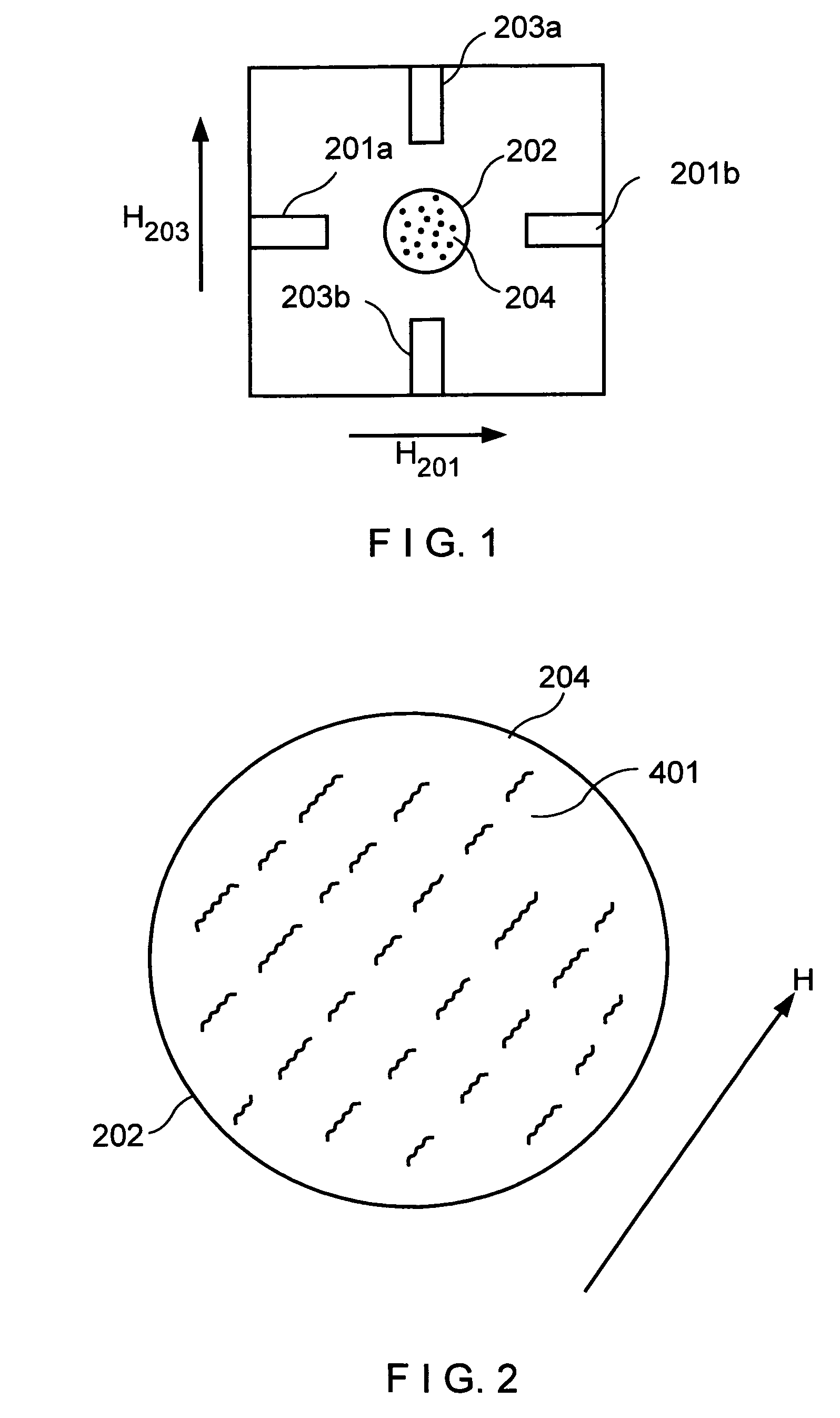
Another disadvantage is that the mixing effect in the conventional Helmholtz coil-based system is substantially limited to the immediate area spanned by the rotating particle chains 401, each of which rotates about its own center.
This makes an inefficient use of the available magnetically inducible particles in the particle suspension area 204.
However, the described conventional magnet-based arrangement also has certain disadvantages.

Method used


Image

  • Method and arrangement of rotating magnetically inducible particles
  • Method and arrangement of rotating magnetically inducible particles
  • Method and arrangement of rotating magnetically inducible particles

Examples


Embodiment Construction

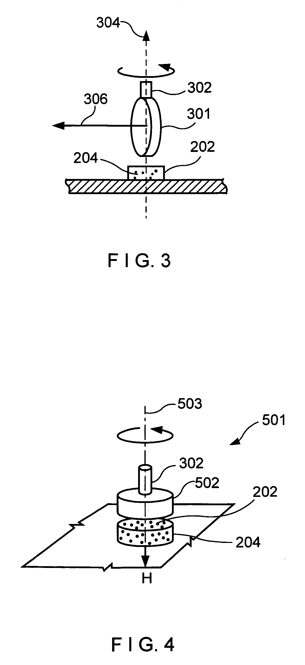
[0028]FIG. 4 is a diagram depicting an arrangement that utilizes a multidirectional magnetic field to rotate a fluid suspension comprising magnetically inducible particles in accordance with a first exemplary embodiment of the present invention. This arrangement preferably comprises a drive shaft 302 and a magnet 502 which are configured to operate on a fluid cell 202 and a particle suspension area 204 contained in the fluid cell 202.

[0029]The fluid cell 202 may be an open or a closed container that holds the particles in the suspension area 204. The particle suspension area 204 comprises a sample of magnetically inducible particles suspended in the fluid to be mixed. These magnetically inducible particles may include paramagnetic microspheres or any other suitable magnetically inducible particles. The magnet 502 can be a rare earth magnet, such as a neodymium iron boron magnet, but may also be a different type of a magnet or another magnetic field source.

[0030]The magnet 502 and th...


PUM


Abstract

This invention provides a device and method for rotating magnetically inducible particles suspended in a fluid by rotating a multidirectional magnetic field through the suspended particles. A rare earth magnet is positioned adjacent to the suspended particles and oriented such that the axis of a magnetic field generated by the magnet passes through the suspension. The magnetic flux lines of the magnet's field radiate in multiple directions through the suspended particles, them to form long multidirectional chains. The magnet and the chains of suspended particles are rotated with respect to one another, the axis of the rotation being approximately parallel to the magnetic axis of the multidirectional magnetic field. This causes the particle chains to rotate about the magnetic axis, thus mixing the fluid.

Description

RELATED APPLICATION[0001]This application is a continuation application and claims priority to International Patent Application No. PCT / US2003 / 019257, filed Jun. 20, 2003, and published in English as Publication No. WO 2004 / 000446 on Dec. 31, 2003, and further claims priority to U.S. Provisional Application No. 60 / 391,073, which was filed on Jun. 20, 2002, both of which are incorporated by reference in their entireties herein.FIELD OF THE INVENTION[0002]This invention relates to methods and arrangements for rotating magnetically inducible particles suspended in a fluid. More particularly, the present invention relates to a method and arrangement for mixing fluids containing such particles by subjecting the particles to a rotating, multidirectional, magnetic field.BACKGROUND OF THE INVENTION[0003]Where the delicate and noninvasive mixing of small-sized fluid samples may be called for, one known technique is to use a rotating magnetic field to mix the fluid. Typically, magnetically in...

Claims


Application Information

Patent Timeline
Patent Type & Authority Patents(United States)
IPC IPC(8): B01F13/08B01F
CPCB01F13/0809B01F33/451
Inventor GARCIA, ANTONIO A.VUPPU, ANIL K.
Owner THE ARIZONA BOARD OF REGENTS ON BEHALF OF THE UNIV OF ARIZONA
Learn More