
Efficient architectures for protection against network failures

a network failure and efficient architecture technology, applied in the field of network failure protection efficiency architectures, can solve the problems of excess network capacity, increased cost, and inability to provide wavelength transformation,

Inactive Publication Date: 2008-03-11
LUCENT TECH INC +1
View PDF22 Cites 24 Cited by
  • Summary
  • Abstract
  • Description
  • Claims
  • Application Information

AI Technical Summary

Benefits of technology

[0009]The present invention provides improved dual-homing techniques for protecting against network failures in an optical network or other type of network.
[0012]Advantageously, the present invention provides improved protection against network failures while requiring less additional capacity than the conventional dual-homing approach described previously. In addition, the invention can provide link level protection against fiber cuts or other failures. Furthermore, the invention ensures that a link failure will not force a switch between a primary dual-homed element and a secondary dual-homed element. The invention also provides a reduction in complexity relative to conventional dual-homed architectures.

Problems solved by technology

A wavelength switching cross-connect serves to cross-connect incoming wavelengths on a given input fiber to different output fibers, but does not provide any transformation in wavelength.
Although this dual-homing approach provides protection against nodal failures, the doubling of demands leads to excess network capacity and hence increased cost.
Unfortunately, the above-described conventional dual homing approach is unable to provide adequate and efficient protection in this application as well as other important applications.

Method used


Image

  • Efficient architectures for protection against network failures
  • Efficient architectures for protection against network failures
  • Efficient architectures for protection against network failures

Examples


Embodiment Construction

[0027]The invention will be illustrated herein in conjunction with the routing of exemplary traffic demands between network elements, also referred to herein as network nodes. It should be understood, however, that the invention is not limited to use with any particular type of traffic demand, network element or network, but is instead more generally applicable to any network traffic routing situation in which it is desirable to provide improved protection against network failures. For example, the network failure protection techniques of the invention may be utilized not only in optical networks, but also in telephone, cable and other electrical networks. The term “network” as used herein is therefore intended to include, e.g., optical networks, electrical networks and hybrid optical-electrical networks.

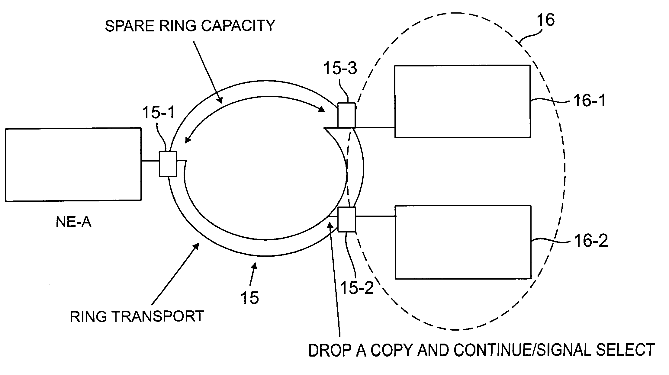
[0028]FIG. 2 shows a portion of a network which incorporates an improved dual-homing approach in accordance with an illustrative embodiment of the invention. The portion of the netw...


PUM


Abstract

Traffic demands are routed between network elements so as to provide improved protection against network failures. A given traffic demand is routed from a first network element to a second network element, where the second network element is preferably either one of a set of dual-homed elements, or coupled to a dual-homed element, and may also be an element of a ring-type transport or a mesh-type transport. The second network element processes the traffic demand such that a copy of a signal associated with the demand is (i) retained at the second network element, while the signal is routed to at least one additional network element, or (ii) routed to at least one additional network element, while the signal is routed to at least one network element other than the additional network element. For example, in a multidrop connection implemented in accordance with the invention, a copy of the signal is “dropped” at the second network element and one or more additional network elements. In a multicast connection implemented in accordance with the invention, one or more copies of the signal are multicast from the second network element to multiple additional network elements.

Description

RELATED APPLICATION[0001]The present application is related to U.S. patent application Ser. No. 09 / 588,490, filed concurrently herewith in the name of inventors B. Doshi and R. Nagarajan and entitled “Methods and Apparatus for Protection Against Network Failures,” which is incorporated by reference herein.FIELD OF THE INVENTION[0002]The present invention relates generally to techniques for protecting an optical network or other type of network from a failure in a link, span, node or other element of the network, and more particularly to techniques which permit traffic to be redirected through the network in the event of such a failure.BACKGROUND OF THE INVENTION[0003]Communication network technology is advancing at a rapid rate. For example, all-optical networks using wavelength division multiplexing (WDM) are currently being deployed for a wide variety of communication applications. WDM techniques allow optical signals having different wavelengths to be multiplexed into a single op...

Claims


Application Information

Patent Timeline
Patent Type & Authority Patents(United States)
IPC IPC(8): H04L12/26H04J3/00H04J3/08H04L12/56H04M3/00H04Q3/52H04Q11/00H04Q11/04
CPCH04J3/085H04Q11/0062H04Q11/0478H04J2203/0032H04J2203/0053H04J2203/006H04J2203/0098H04Q2011/0073H04Q2011/0083H04Q2011/0092
Inventor NAGARAJAN, RAMESH
Owner LUCENT TECH INC
Learn More