
Dental implant method and apparatus

Inactive Publication Date: 2008-03-11
COATOAM GARY W
View PDF20 Cites 12 Cited by
  • Summary
  • Abstract
  • Description
  • Claims
  • Application Information

AI Technical Summary

Benefits of technology

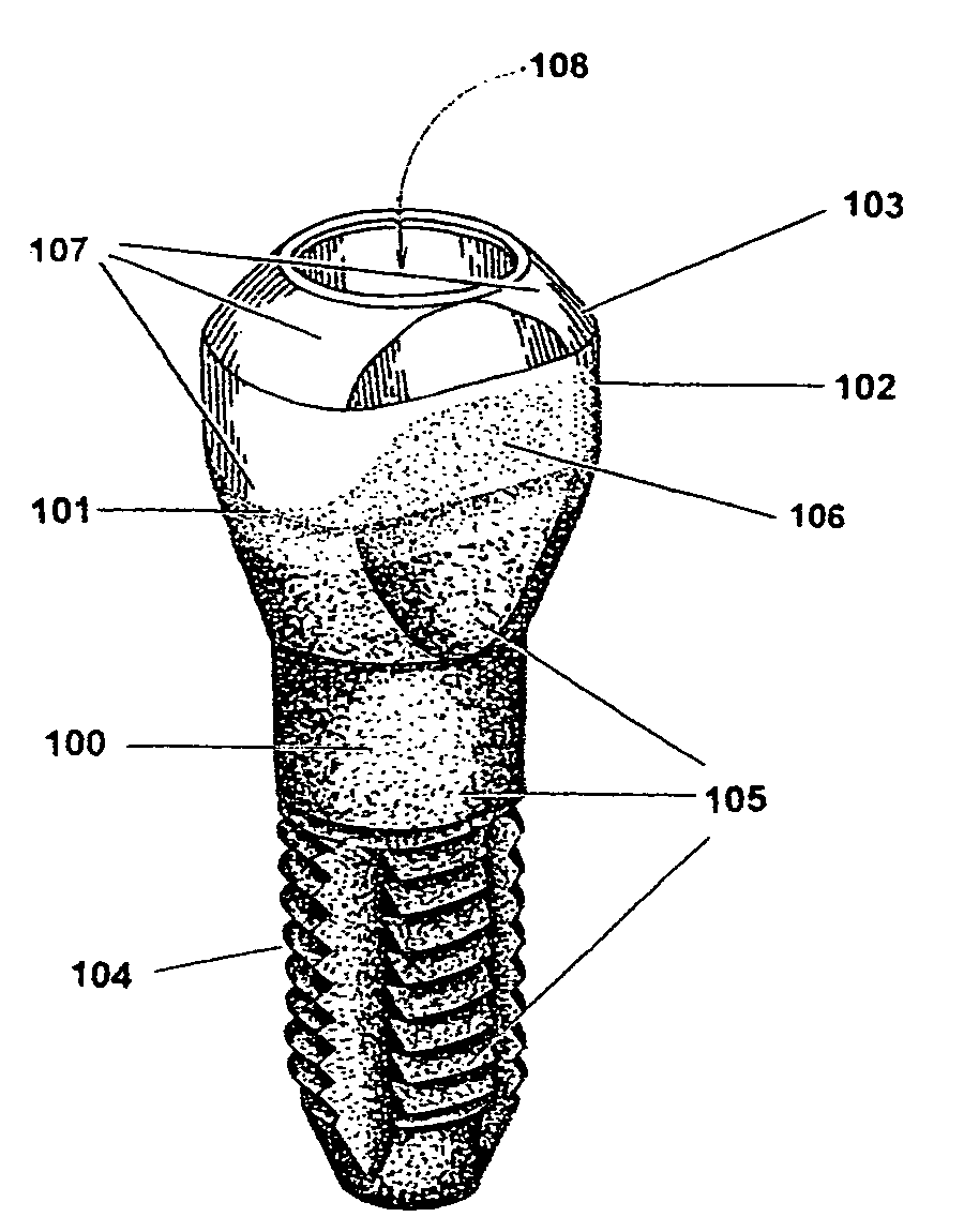
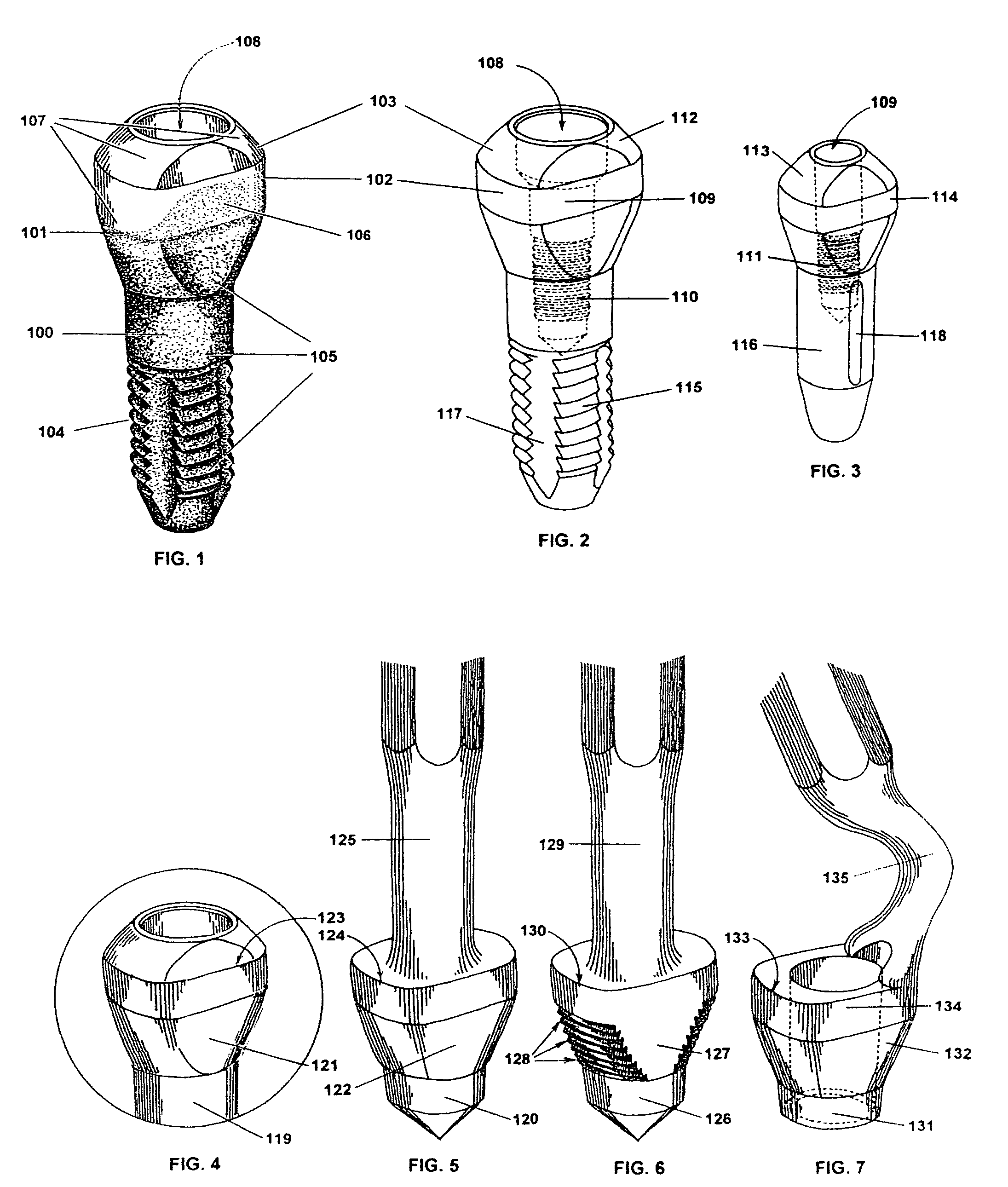
[0012]The proximal end of the implant extends out of the prepared hole in the bone. The proximal ends of the implants have gently rounded, convex amalgamated anatomical abutment bases. The amalgamated abutment base may be partially coated with gold, porcelain, gold-colored titanium nitrite or other substances used to improve aesthetics. The amalgamated abutment may have a bored hole to accommodate various extenders. This bored hole may be non-round, but the actual anatomical shape of the abutment base or Morse taper of the round abutment provides the essential anti-rotational component to the implant. For that reason the shape of this tube-like extension is not critical since any non-round design of this opening may be a redundancy in regard to anti-rotational design. This would also be true of non-round proximal extensions of the abutment base such as hexes, slots, or splines, which might be thought to alter this invention, but would not enhance the design. It is also nonessential that any abutment extender has an indexed shape to prevent crown rotation. The crown is prevented from rotating by direct attachment to the anatomically shaped implant / abutment head.
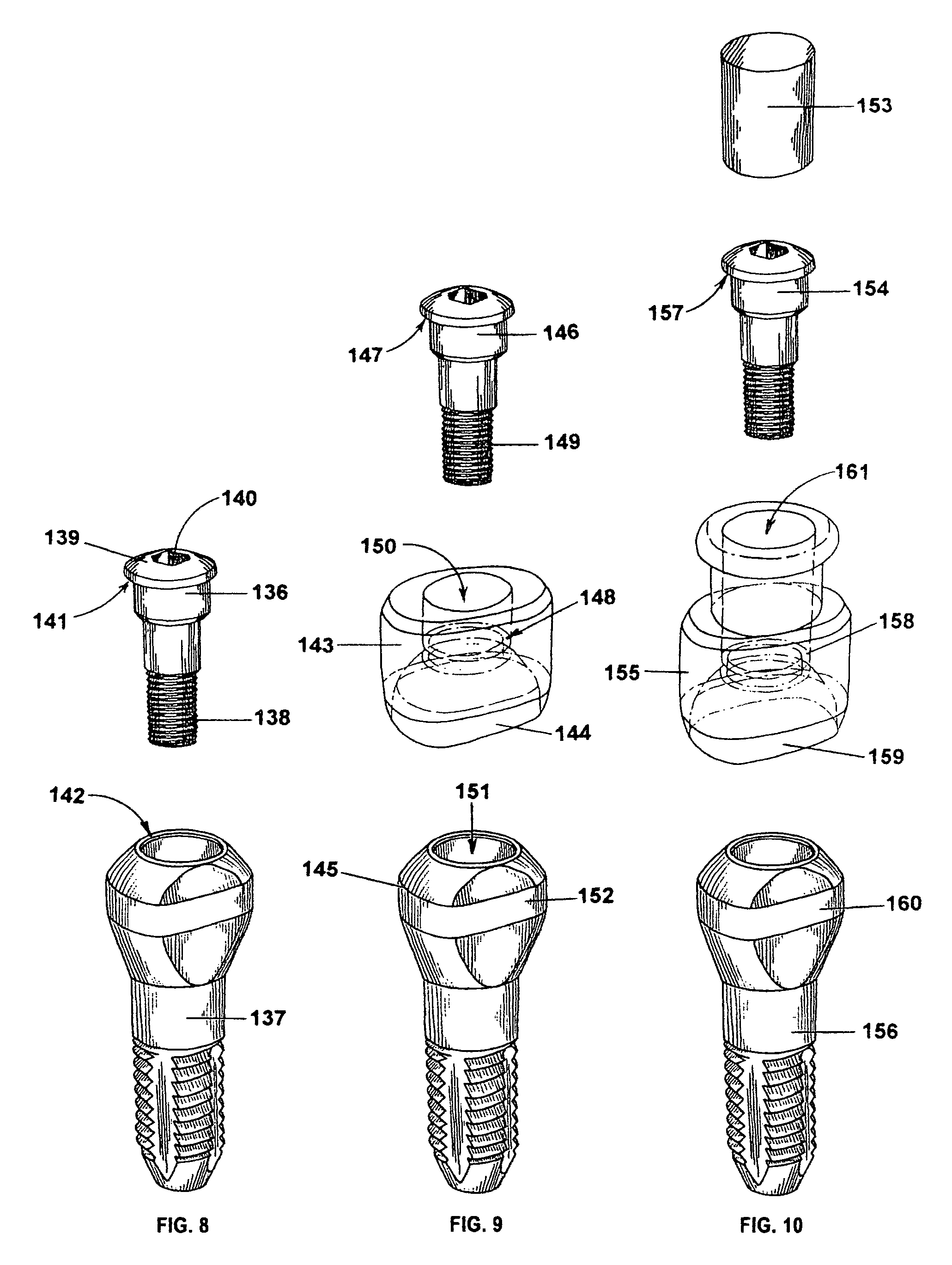
[0013]At the bottom of the bore opening there is a threaded extension of the bored opening. This threaded extension can receive a threadedly inserted screw or non-threadedly inserted rod extension. The proximal end can accommodate various fittings that act as posts for a crown and post design or for post and core extenders that will provide added retention to subsequent dental crown prosthesis. This feature facilitates the placement of angled post and core extenders and anatomic coping attachments that are in keeping with dental technology that has been used to restore natural teeth for many years. The doctors' familiarity with these common dental techniques is a meaningful strength of this system.

Problems solved by technology

Because implant abutments are subject to rotational loosening, the dental prosthesis, which is subsequently affixed to the post attachments, is also subject to this unscrewing phenomenon.
This can lead to loosening and failure of the dental prosthesis.
In each case the seam between the implant and the abutment presents a problem after surgical implant placement because of subsequent bone dieback.
It is also necessary to keep the edge of the implant in a position above the crest of bone because even though the crown margin finishes on the implant body, that margin may also act as a microgap that can lead to bone loss.

Method used


Image

  • Dental implant method and apparatus
  • Dental implant method and apparatus
  • Dental implant method and apparatus

Examples


Embodiment Construction

[0026]Referring to the drawings, and particularly FIG. 1, a dental implant with a cylindrical body 100, and an anatomically shaped proximal end 101, has nearly parallel walls 102, and has an integrated anatomically shaped abutment base 103 formed as part of the implant and not a separate attachment. Transitional nearly parallel walls 102 between the abutment and the implant adjoin the abutment base to the implant. These walls may have a slight convergence in the coronal direction to facilitate draw of the prosthetic component. This entire assembly is preferably made from titanium or an alloy thereof, and may be cut from one piece of stock material. If the implant body is made of a different material than that of the integrated abutment, the two pieces are permanently fused without any microgap being present after fusion of the parts. This integrated or amalgamated abutment eliminates any abutment / implant seam below the bone or gum tissue. The seam has been implicated in bone die bac...


PUM


Abstract

A dental implant (105,137,156) has an elongated body (100) having first and second end portions (101,103) and having a root on one end portion (104,115,116) for attaching to a patient's jawbone to replace the root of a removed tooth. The root portion (104,115,116) has an anatomically shaped portion between the end portions of the body for fitting into a jawbone opening below the gum tissue of a patient when the root (104,115,116) is attached to a jawbone. An artificial tooth abutment (103,112&113) is formed on the other end of the elongated body for attaching an artificial tooth thereon of the abutment extending above the gum line of a patient. A method of attaching a dental implant (105,137,156) includes the steps of extracting a patient's tooth and selecting the dental implant (105,137,156) of the apparatus and attaching the dental implant root (104,115,116) with the jawbone of a patient with the abutment (103,112,113) extending above the gum tissue of the patient and attaching the artificial tooth to the abutment.

Description

[0001]This is a division of patent application Ser. No. 10 / 286,490, filed Nov. 1, 2002 now abandoned for a Dental Implant Method and Apparatus .BACKGROUND OF THE INVENTION[0002]1. Field of the Invention[0003]The present invention relates generally to the field of dental implants and in particular to a system of anatomic dental implants, which may be converted to an anatomic facsimile of a natural tooth. The present invention also relates to eliminating the quandary of having to decide if the implant / abutment seam will compromise aesthetics or if the implant / abutment seam will compromise the integrity and long-term of the bone. The present invention also relates to ancillary components and instruments related to the placement and restoration of the anatomic implant.[0004]2. Background of the Invention[0005]A dental implant is an artificial tooth made of metal with a porcelain coating designed to make it look real. Its most important component is its root, a titanium anchor that is su...

Claims


Application Information

Patent Timeline
IPC IPC(8): A61C8/00A61C3/00
CPCA61C8/005A61C8/0075A61C8/0089A61C8/008
Inventor COATOAM, GARY W.
Owner COATOAM GARY W
Learn More