
Load-balancing distributed raster image processing

Active Publication Date: 2008-03-04
SHARP KK
View PDF16 Cites 13 Cited by
  • Summary
  • Abstract
  • Description
  • Claims
  • Application Information

AI Technical Summary

Benefits of technology

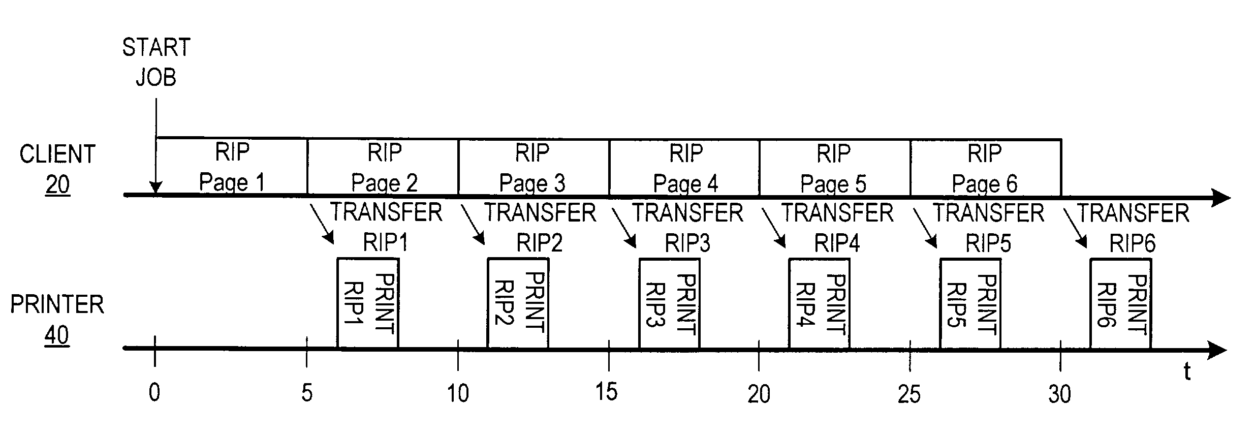
[0005]It is recognized herein that a different approach can achieve multi-processing efficiencies in print processing, without the complexities and inefficiencies that attend the prior-art parallel-print-processing approaches. The approach described in the embodiments herein is based on the observation that in most environments a print job naturally passes through multiple processing nodes before a marking engine finally transfers the contents of that print job to paper or other media. For instance, even with a single client hardwired to a printer, a print job originates on the client (which has a processor), and is then transferred to the printer (which, if capable of rasterization, has a separate processor). The rasterization load can be balanced between the client and printer by, e.g., having the client rasterize every other page in the print job and send the print job to the printer in a mixed format, with some pages in raster format and some pages in PDL format. The printer rasterizes the remaining pages as it receives them in the print job, and thus the rasterization load is halved on both devices. The client and the printer rasterize the print job in what can be viewed as a serial or pipeline approach, where each touches a part of the print job as it passes through. Once the “pipeline” is filled, the efficiency of this approach is in all likelihood much better than the efficiency of a parallel scatter-gather approach, and requires fewer processing and storage resources to accomplish.
[0006]Similar serial approaches can be used with a Raster Image Processing (RIP) Server that accepts print jobs from networked clients, rasterizes (or “RIPs”) the print jobs, and then submits them to one of possibly several supported printers for printing. In one embodiment, the RIP server can accept a PDL print job, rasterize some pages of the print job, and then transfer a mixed raster / PDL format print job to the printer (which completes rasterization as described in the preceding example). In another embodiment, the client can rasterize some pages, transfer a mixed raster / PDL format print job to the RIP server, and then the RIP server completes rasterization and transfers a raster file to the printer. In a third embodiment, the client, RIP server, and printer could each process some pages of the print job. These embodiments can allow a less-powerful RIP server to run one or more printers at maximum marking speed by relying in part on client and / or printer processing resources to complete rasterization.
[0008]In other embodiments, the devices can coordinate their loads with each other, and thus the question of which pages are processed by which device can remain more fluid. For instance, a RIP server that serves multiple printers may accept a larger proportion of a print job for rasterization when only one of its printers has a job pending than it accepts when it has jobs for multiple printers pending. A printer (or RIP server) could also communicate its rasterization progress or current loading upstream, so that an upstream processor can determine when to pass another PDL-format page to the printer.

Problems solved by technology

For inkjet and other low-cost printers, the rasterization process is typically performed on the user's computer, and may cause a noticeable slowdown in computer response while rasterization is proceeding.
Although parallel processing has many applications to which it is ideally suited, those applications (e.g., weather prediction, complex simulations) are generally orders of magnitude more complex than document printing.
But for most network configurations it is questionable as to whether the increased print processing software size and complexity in all processing nodes, possibility of errors in partitioning and reassembly, and increased network traffic due to multiple back-and-forth print data transfers across the network are worth the speed benefit gained.

Method used


Image

  • Load-balancing distributed raster image processing
  • Load-balancing distributed raster image processing
  • Load-balancing distributed raster image processing

Examples


Embodiment Construction

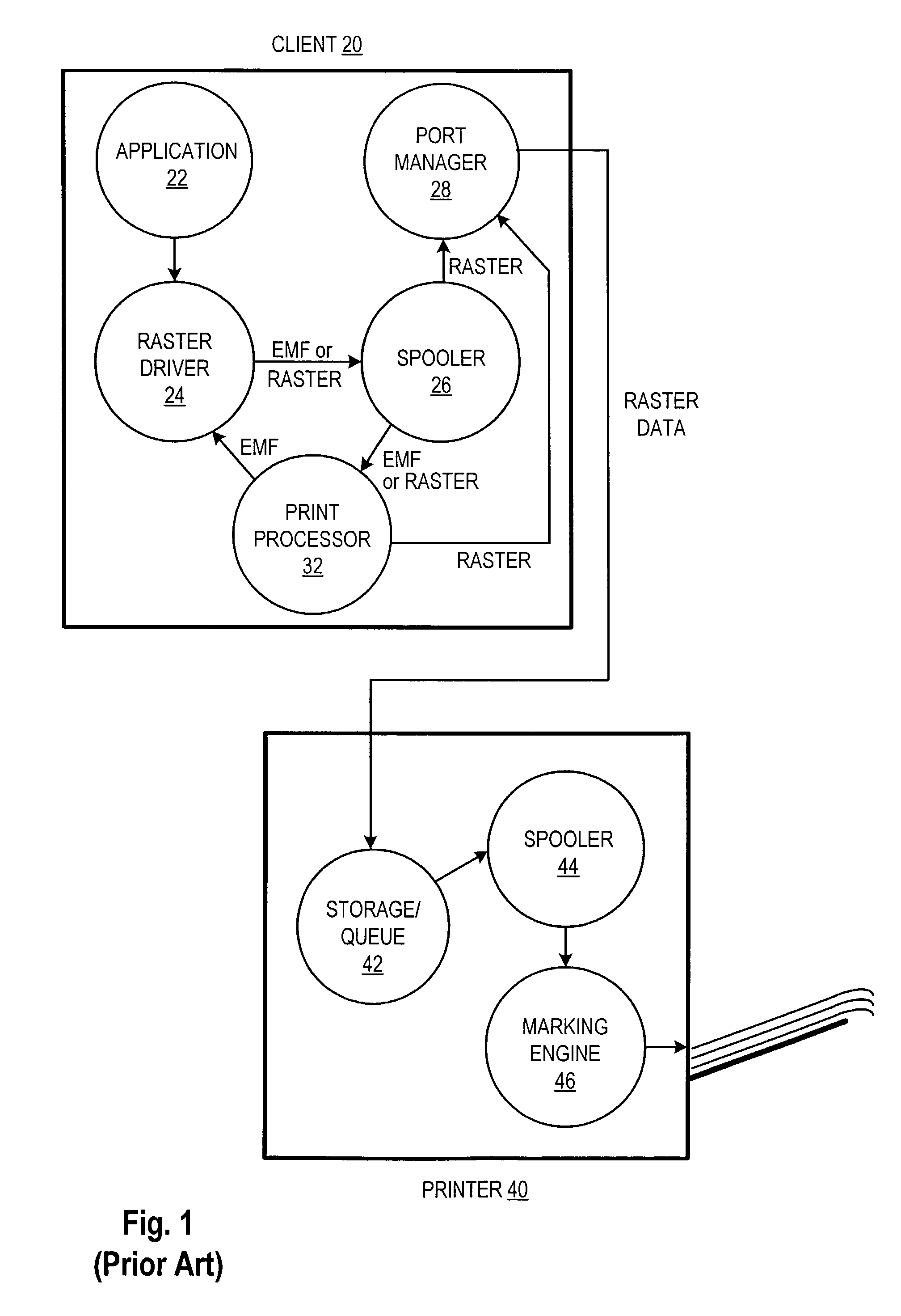
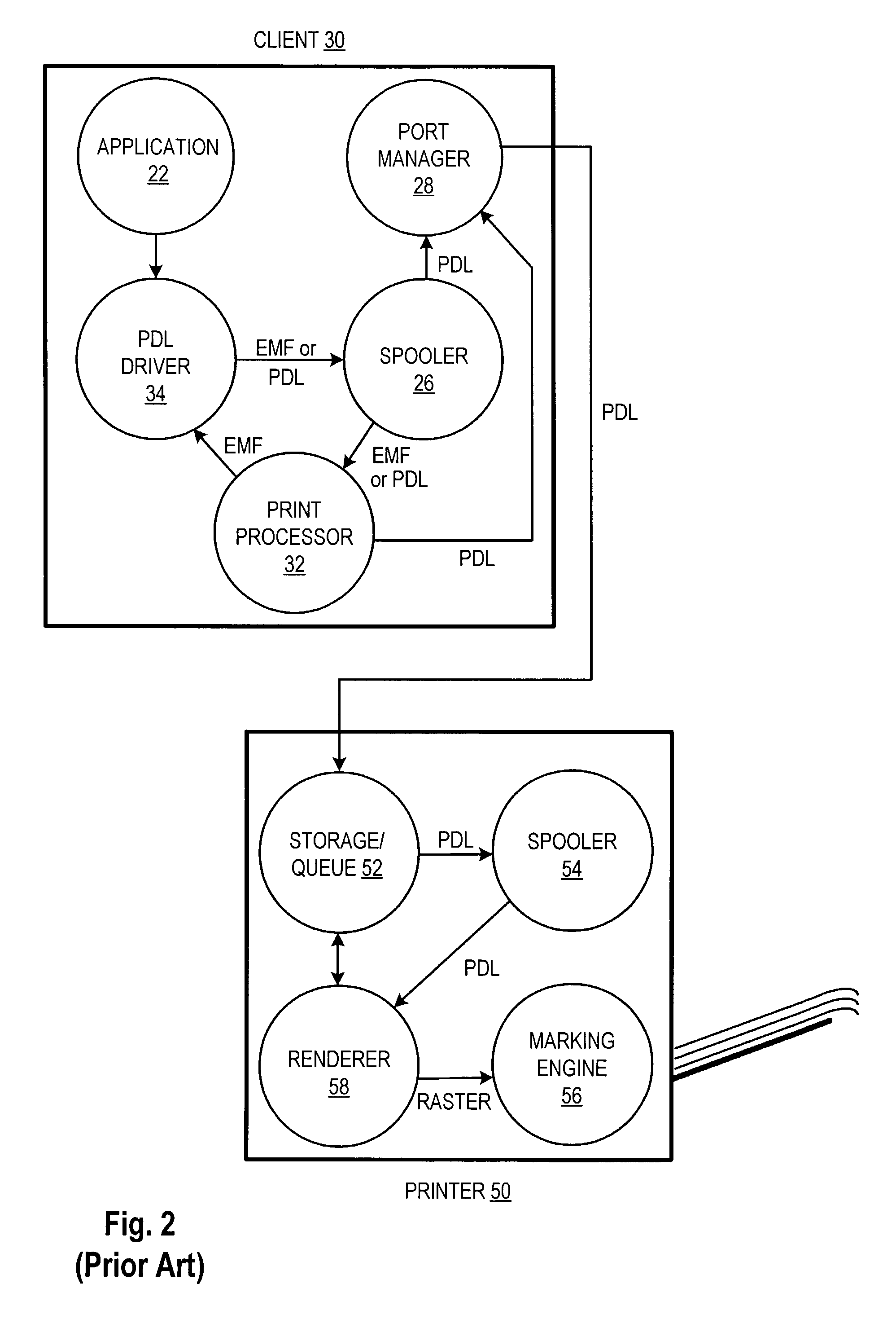
[0019]The advantages and operational differences of the embodiments are perhaps best understood by comparison to traditional print processing configurations. Accordingly, this description begins with a description of typical client, RIP server, and printer operation in a Microsoft Windows-type environment.

[0020]FIG. 1 shows a client 20 and a basic printer 40. Client 20 runs applications, such as application 22, that generate graphical output as a set of instructions to a generic Windows-compatible display device.

[0021]When, e.g., a user or scheduled task prompts application 22 to print a document, application 22 passes the graphical instructions for printing the document to raster driver 24. Raster driver 24 is typically supplied by the manufacturer of printer 40, and is adapted to translate Windows-format graphical instructions to a printer-specific format. Driver 24 can either journal or render the instructions at this point to create a print job. When the data is rendered, driver...


PUM


Abstract

A method and apparatus for raster processing print data wherein multiple print-processing nodes process a print stream serially as it passes through those nodes. For instance, a client generates a print job with some pages in raster format and some pages in a Page Description Language (PDL) format, e.g., every other page. The pages are encapsulated with Printer Job Language commands that allow a printer to detect which pages in the mixed-format stream are in which format. The printer prints raster-format pages directly, and sends PDL-format pages to an internal renderer before submitting them to its marking engine. This arrangement allows printing, e.g., at full-marking-engine speed, on a printer with a low-speed renderer and from a client that can only render pages at low speed.

Description

FIELD OF THE INVENTION[0001]The present invention relates generally to printing and printing system devices, and more particularly to systems and methods for sharing rasterization tasks among several print system devices.BACKGROUND OF THE INVENTION[0002]Document printing is a familiar task to just about anyone who has worked with a computer. Many computer users have had the experience (whether they recognized it or not) of requesting document printing and then having to wait while, somewhere in the print path, the document was rasterized (i.e., placed in the format required for the printer marking engine). For inkjet and other low-cost printers, the rasterization process is typically performed on the user's computer, and may cause a noticeable slowdown in computer response while rasterization is proceeding. For most other printers, the user's computer generates a Page Description Language (PDL)-format print file, such as a PostScript file. The printer interprets the PDL-formatted da...

Claims


Application Information

Patent Timeline
IPC IPC(8): G06F3/12G06F15/00G06K1/00H04L29/06H04L29/08
CPCG06F3/1211G06F3/1247G06F3/1248G06F3/1285H04L67/1002H04L67/1001
Inventor FERLITSCH, ANDREW R.
Owner SHARP KK
Learn More