
Image recording apparatus

a technology of image recording and recording frame, which is applied in the direction of typewriters, printing, inking apparatus, etc., can solve the problems of deterioration of text character quality, and achieve the effect of high quality of text character

Inactive Publication Date: 2008-03-04
KONICA MINOLTA INC
View PDF11 Cites 4 Cited by
  • Summary
  • Abstract
  • Description
  • Claims
  • Application Information

AI Technical Summary

Benefits of technology

[0008]The objective of the present invention is to provide an image recording apparatus which is capable of producing high quality of text characters which have been printed in black ink.
[0009]Further, the objective of the present invention is to provide an image recording apparatus which is capable of improving the sharpness of the color image and sharpening the image quality. The objective of the present invention can be attained by the structures described below.
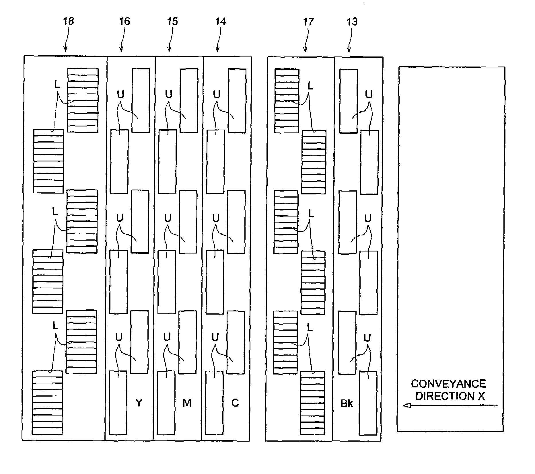
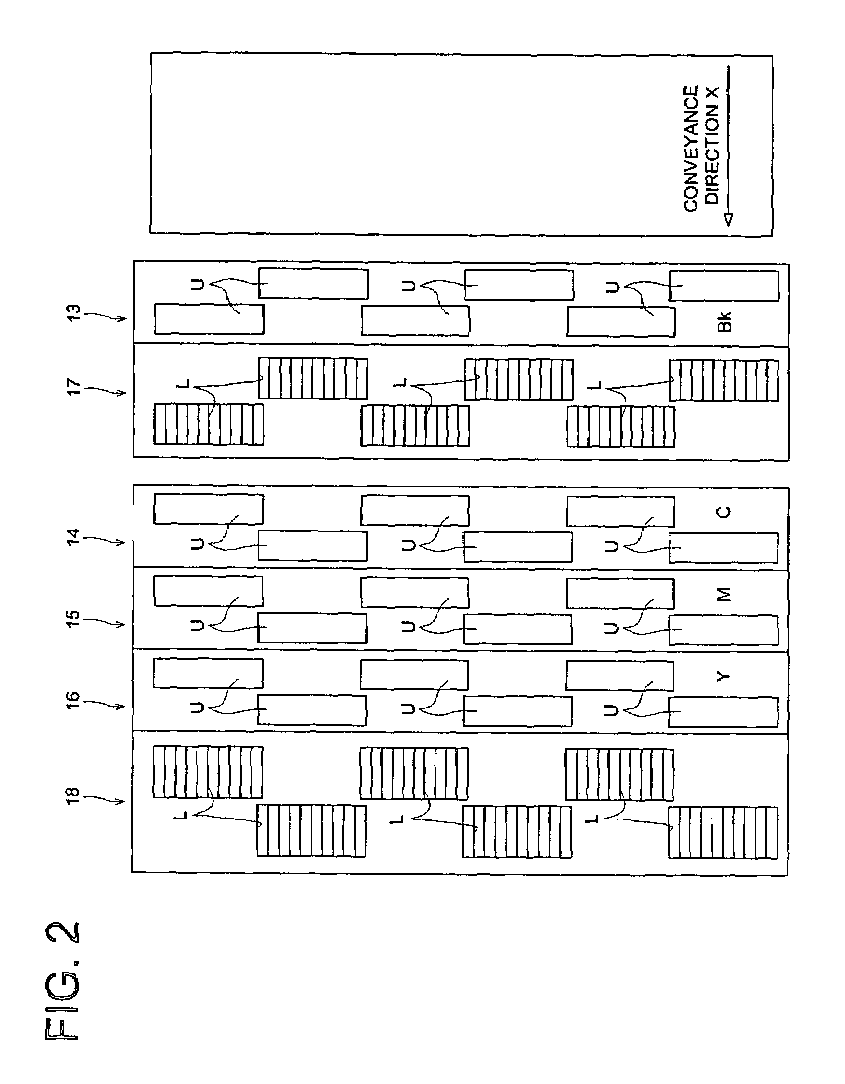
[0018]According to structure 1, since the first light radiating device is arranged downstream of the black printing head, before the color ink drops are ejected, the first light radiating device radiates light rays onto the black ink drops which have been landed on the recording medium sheet, and thereby the black ink drops are hardened. Further, since the second light radiating device is arranged downstream of the color printing head which is most downstream among all of the color printing heads, the second light radiating device radiates the light rays onto the color ink drops which landed on the recording medium sheet after the black ink have been hardened, and then the color ink drops are also hardened. Accordingly, the color and black ink drops are hardened without being contaminated, resulting in improvement of image quality of the text characters printed in black ink.
[0030]According to structure 3, since the first light radiating device is arranged downstream of the color printing head which is most downstream among all of the color printing heads, before the black ink drops are ejected, the first light radiating device radiates light rays onto the color ink drops which have been landed on the recording medium sheet, and thereby the color ink drops are hardened. Further, since the second light radiating device is arranged downstream of the black printing head, the second light radiating device radiates the light rays onto the black ink drops landed on the recording medium sheet after the color ink drops have been hardened, and then the black ink drops are also hardened. Accordingly, the color and black ink drops are hardened without being mixed. Specifically, the black ink drops are landed after the color ink drops have been hardened, resulting in improvement of image quality, and thereby, the color images having the sharp image quality are produced.

Problems solved by technology

Since a text character is generally recorded in black ink, if color or black ink are mixed, specifically when the character is recorded on the recording medium sheet, edges of the black text character become blurred at the area where the black recording overlaps the color recording, resulting in deterioration of text character quality, which is not preferable.

Method used


Image

  • Image recording apparatus
  • Image recording apparatus
  • Image recording apparatus

Examples


first embodiment

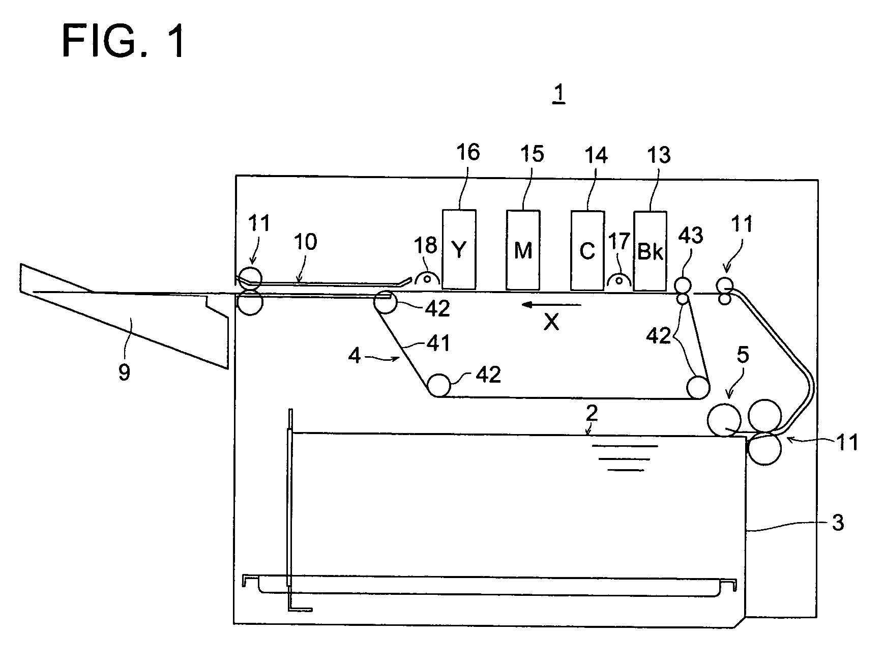
[0043]FIG. 1 is a drawing of a first embodiment of the image recording apparatus relating to the present invention. In a lower interior portion of image recording apparatus 1, accommodation tray 3 is provided on which plural recording media sheets 2 are stacked. Above one of the ends of accommodation tray 3, take-up device 5 is provided which takes up recording media sheets 2 one by one, on which images are to be recorded, from accommodation tray 3. In this case, concerning recording media sheets 2, it is possible to employ cut sheets selected from various kinds of paper such as plain paper, recycled paper, and glossy paper, various kinds of cloth, various kinds of bonded textiles, and cut sheet of materials such as resin, metal, and glass.

[0044]Above accommodation tray 3, conveyance device 4 is provided which conveys recording media sheets 2. In this conveyance device 4, endless conveyance belt 41 rotates about entrained plural rollers 42 so that conveyance belt 41 makes it possibl...

second embodiment

[0074]FIG. 7 is a drawing of a second embodiment of the image recording apparatus 1a relating to the present invention. In a lower interior portion of image recording apparatus 1a, accommodation tray 3 is provided on which plural recording media sheets 2 are stacked. Above one of the ends of accommodation tray 3, take-up device 5 is provided which takes up recording media sheets 2 one by one, on which images are to be recorded, from accommodation tray 3. In this case, concerning recording media sheets 2, it is possible to employ cut sheets selected from various kinds of paper such as plain paper, recycled paper, and glossy paper, various kinds of cloth, various kinds of bonded textiles, and cut sheet of materials such as resin, metal, and glass.

[0075]Above accommodation tray 3, conveyance device 4 is provided which conveys recording media sheets 2. In this conveyance device 4, endless conveyance belt 41 rotates about entrained plural rollers 42 so that conveyance belt 41 makes it po...


PUM


Abstract

An image printing apparatus including a conveyance-printing section for printing on a recording medium sheet; a first printing device including a plurality of black printing heads for jetting image-setting black ink drops onto the recording medium sheet; a second printing device including a plurality of color printing heads for jetting image-setting color ink drops onto the recording medium sheet; first light radiating devices which radiate ultraviolet rays to harden the image-setting black ink drops; and second light radiating devices which radiate the ultraviolet rays to harden the image-setting color ink drops.

Description

BACKGROUND OF THE INVENTION[0001]The present invention relates to an image recording apparatus, and in particular, to an image recording apparatus in which image-setting ink is employed.[0002]In recent years, a great number of the image recording apparatuses using ink-jet recording methods have been used. Because the ink-jet recording method can form images very conveniently at low cost, compared to a method in which a plate-making is required, such as a photogravure printing and a flexographic printing.[0003]Further, in the field where images are recorded on commercial products or on their packaging by the ink-jet method, materials such as resin and metal, having no ink absorbing property, are often used for commercial products and their packaging. In order to fix ink drops on a recording medium sheet having no ink absorbing property, image-setting ink is used. Namely, well known is an image recording apparatus using such image-setting ink, wherein after the image-setting ink drops...

Claims


Application Information

Patent Timeline
IPC IPC(8): B41J2/01B41J3/54B41J11/00
CPCB41J3/543B41J11/002B41J2202/20B41J11/00214B41J11/00212
Inventor HASEBE, TAKASHISHIMIZU, SABUROARAI, TAKEOMASUMI, SATOSHISEKINE, TETSUHAMADA, SHUTA
Owner KONICA MINOLTA INC
Learn More