
Magnetic resonance imaging apparatus

a magnetic resonance imaging and apparatus technology, applied in the field of magnetic resonance imaging apparatus, can solve the problem that the fat suppression pulse of the above mentioned fat suppression pulse is unsuitable for imaging in the ssfp state, and achieve the effect of reducing the time for the transformation

Inactive Publication Date: 2008-02-26
GE MEDICAL SYST GLOBAL TECH CO LLC
View PDF14 Cites 7 Cited by
  • Summary
  • Abstract
  • Description
  • Claims
  • Application Information

AI Technical Summary

Benefits of technology

[0023]Preferably, the separating means separates water data and fat data after correcting a phase error in the Fourier-transformed data due to magnetic field inhomogeneity so that the separation into water and fat may be suitably achieved.
[0024]Preferably, the separating means corrects the phase error by a phase distribution multiplied by 1 / m, after multiplying the phase of the Fourier-transformed data by m to make water and fat in phase and correcting wraparound of a portion beyond a range of ±π so that the phase error correction may be suitably achieved.
[0029]Preferably, the transforming means conducts Fourier transformation from the F(0) term to F(1) term so that the time for the transformation may be reduced.
[0030]Preferably, the apparatus further comprises correcting means for correcting a phase offset and a time offset between a gradient echo and a spin echo so that imaging in the SSFP state may be suitably achieved.

Problems solved by technology

Fat suppression by the aforementioned fat suppression pulses is unsuitable for imaging in the SSFP state because the steady state is disturbed.

Method used


Image

  • Magnetic resonance imaging apparatus
  • Magnetic resonance imaging apparatus
  • Magnetic resonance imaging apparatus

Examples


Embodiment Construction

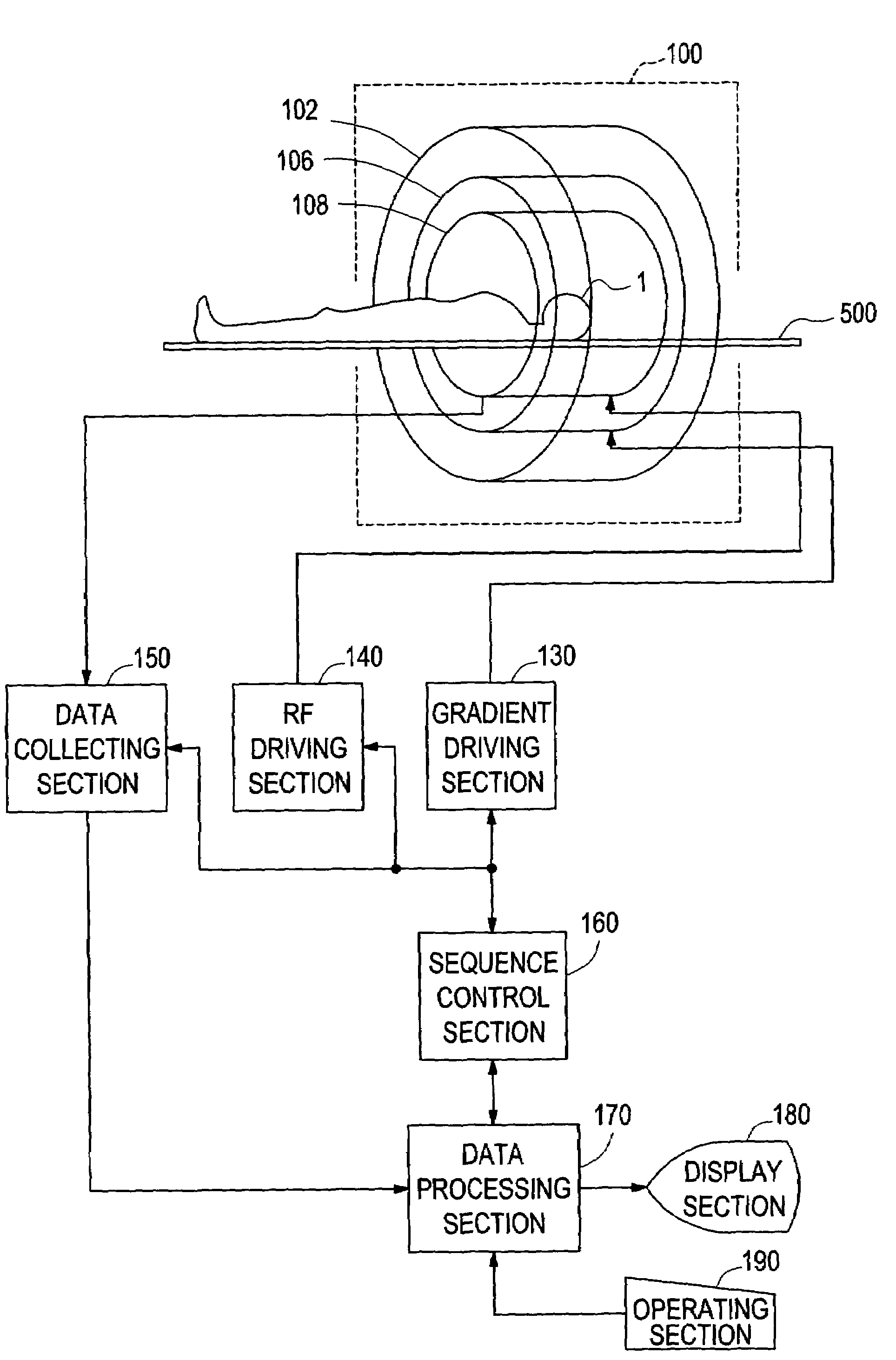
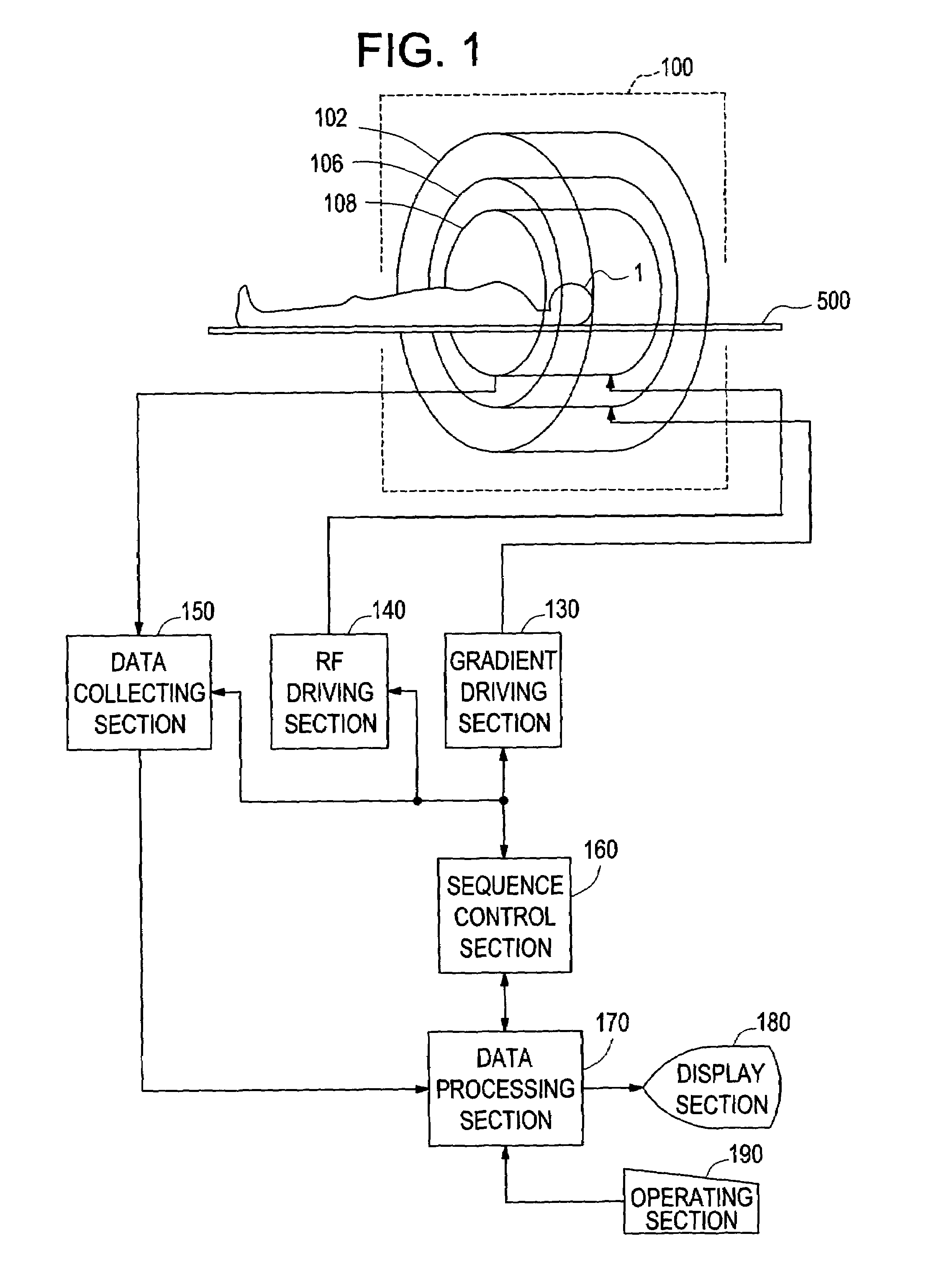
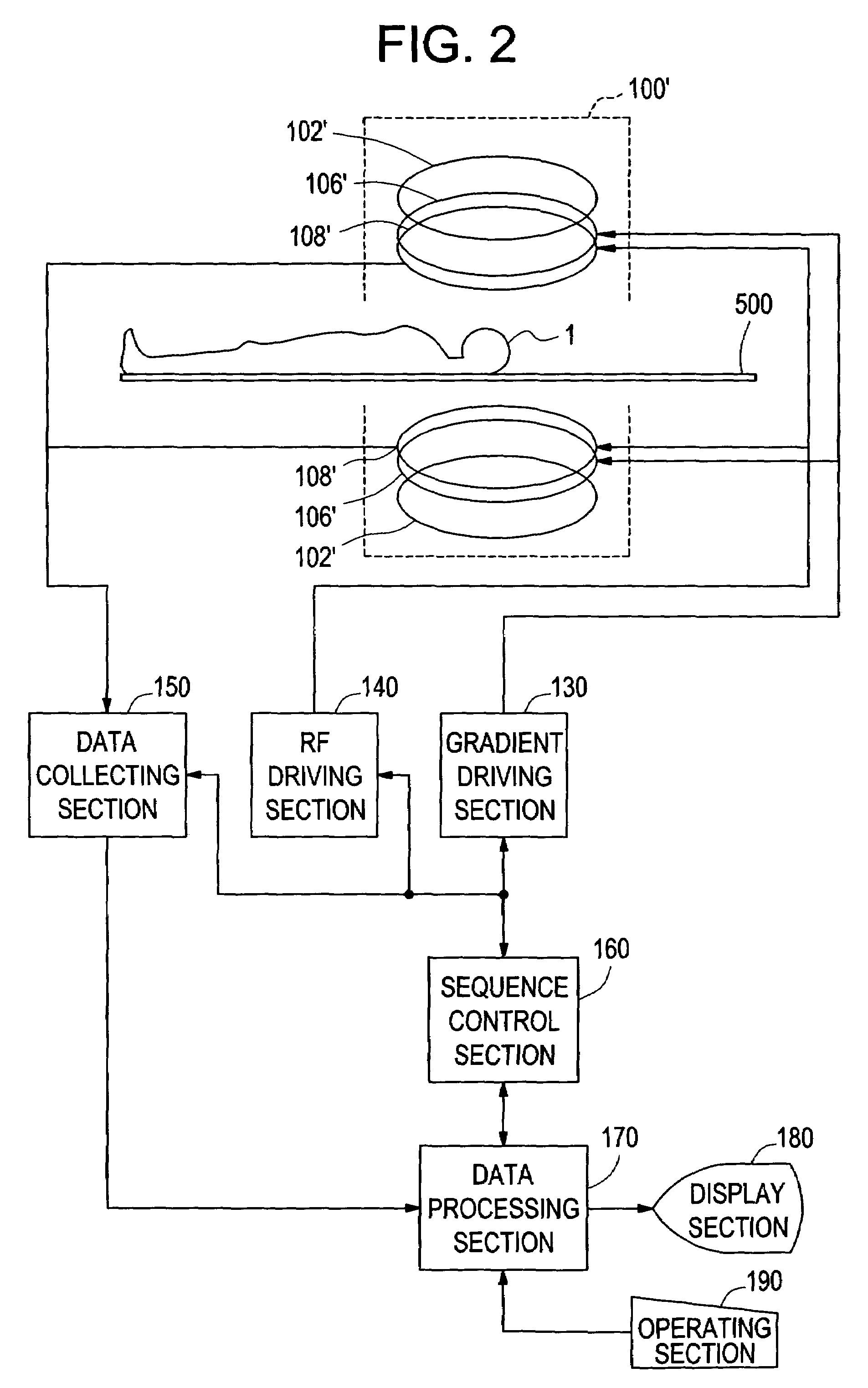
[0049]Embodiments of the present invention will now be described in detail with reference to the accompanying drawings. FIG. 1 shows a block diagram of a magnetic resonance imaging apparatus, which is an embodiment of the present invention. The configuration of the apparatus represents an embodiment of the apparatus in accordance with the present invention.

[0050]As shown in FIG. 1, the present apparatus has a magnet system 100. The magnet system 100 has a main magnetic field coil section 102, a gradient coil section 106, and an RF coil section 108. These coil sections have a generally cylindrical shape and are concentrically disposed. A subject to be imaged 1 is rested on a cradle 500 and carried into and out of a generally cylindrical internal space (bore) of the magnet system 100 by carrier means, which is not shown.

[0051]The main magnetic field coil section 102 generates a static magnetic field in the internal space of the magnet system 100. The direction of the static magnetic f...


PUM


Abstract

An apparatus includes acquiring means for acquiring echo data of a plurality of views in which a phase difference between water and fat is 2π / m with spins within a subject brought to the SSFP state and repeating the acquisition for k=0 through M−1 with a step difference in a phase of an RF pulse of 2π·k / M; transforming means for conducting Fourier transformation on the echo data based on the phase step difference; separating means for separating water data and fat data respectively in F(0) term and F(1) term of the Fourier-transformed data using the phase difference between water and fat; adding means for obtaining a sum of absolute values of at least the water data or fat data in the F(0) term and F(1) term; and image producing means for producing an image based on the sum data.

Description

CROSS REFERENCE TO RELATED APPLICATIONS[0001]This application claims the benefit of Japanese Application No. 2002-288535 filed Oct. 1, 2002.BACKGROUND OF THE INVENTION[0002]The present invention relates to a magnetic resonance imaging apparatus, and more particularly to an apparatus for conducting magnetic resonance imaging with spins within a subject brought to an SSFP (steady state free precession) state.[0003]One conventional technique for conducting magnetic resonance imaging is a method of conducting magnetic resonance imaging with spins within a subject brought to an SSFP state. The method produces an image based on a sum of or a difference between echo data acquired with an RF (radio frequency) pulse having an invariant phase and echo data acquired with an RF pulse having a phase alternating between 0 and π (see, for example, Patent Document 1).[0004]Conventional techniques for suppressing fat signals in magnetic resonance imaging include a method employing a fat suppression ...

Claims


Application Information

Patent Timeline
IPC IPC(8): A61B5/05A61B19/00G01V3/00A61B5/055G01R33/48G01R33/54G01R33/561
CPCG01R33/4828G01R33/5613A61B5/055
Inventor MIYOSHI, MITSUHARUKOSUGI, SUSUMU
Owner GE MEDICAL SYST GLOBAL TECH CO LLC
Learn More