
Peer-to-peer cloud-split detection and repair methods

a technology of peer-to-peer and cloud split, applied in the field of peer-to-peer cloud split detection and repair methods, can solve problems such as inconsistent or disabled partition communication among partitions

Inactive Publication Date: 2008-02-26
MICROSOFT TECH LICENSING LLC
View PDF6 Cites 13 Cited by
  • Summary
  • Abstract
  • Description
  • Claims
  • Application Information

AI Technical Summary

Benefits of technology

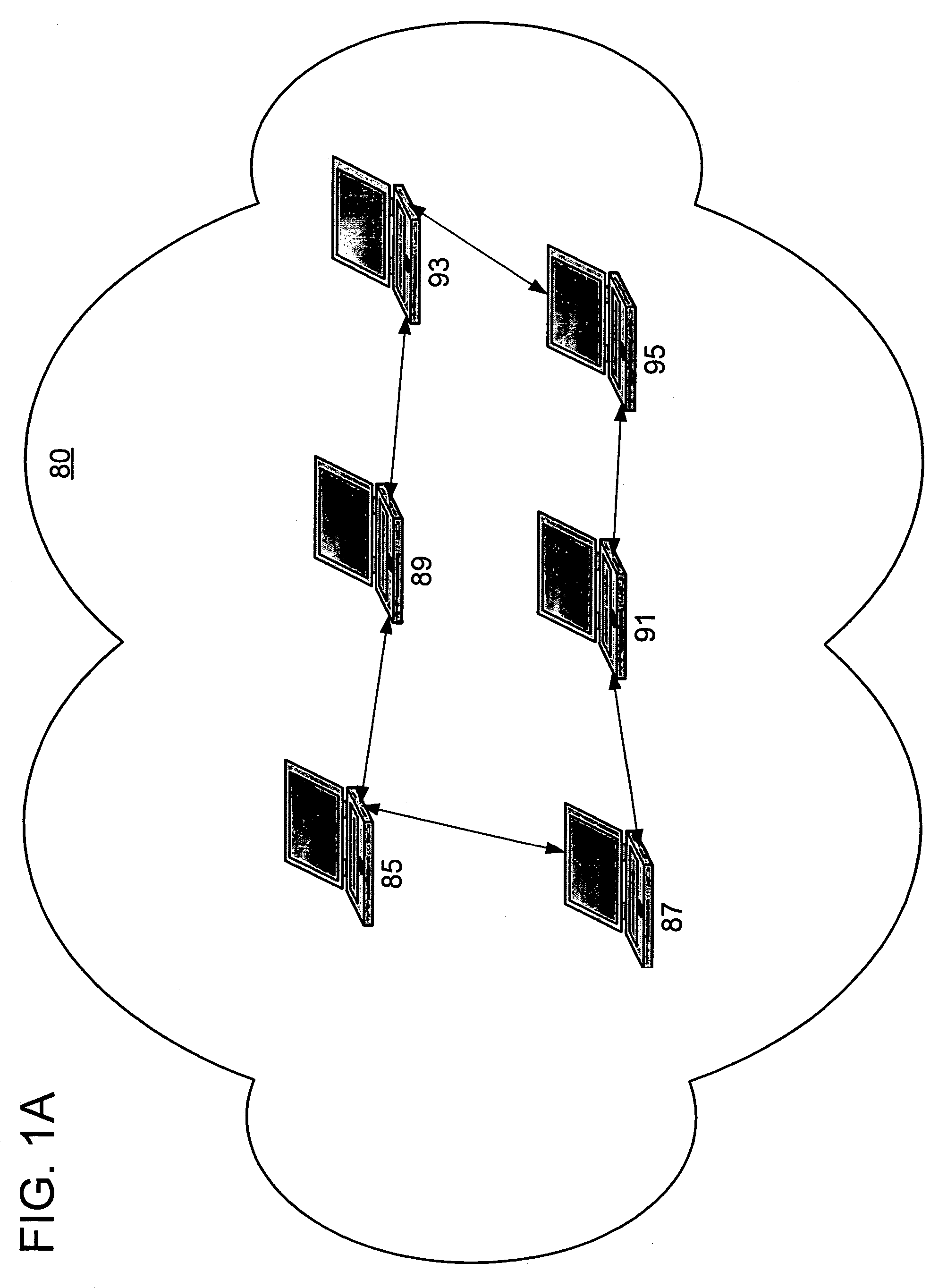
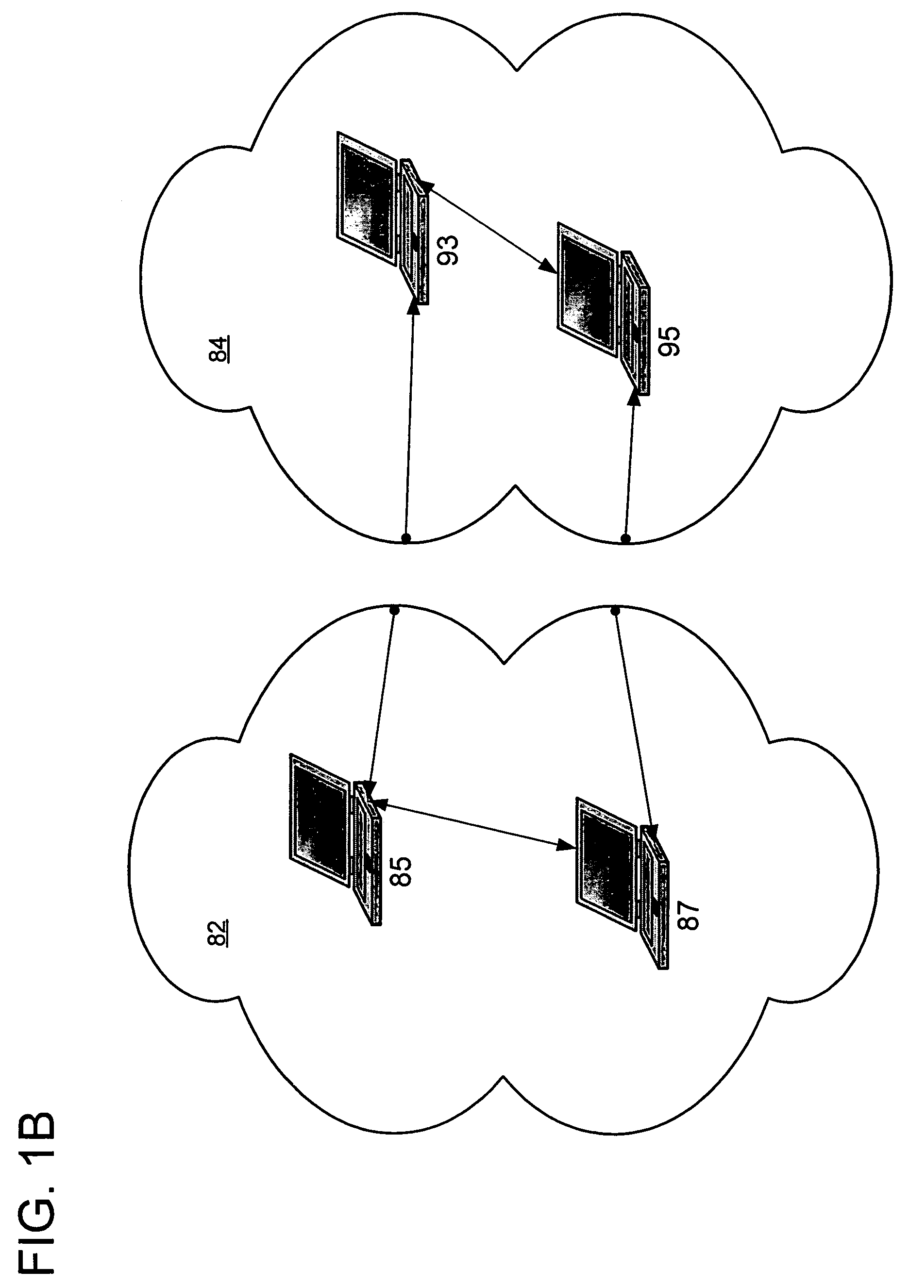
The present invention provides methods for a peer-to-peer network to detect and repair splits in a cloud. Each node in the network is assigned a unique peer identifier and maintains a cache of peer IDs for known nodes. When a split is detected, a resolve message is sent to a well-known node in the cloud, requesting address information. The best-match node is determined and its address information is sent to all nodes in the network. Nodes in the cache record the address information of the best-match node and send it to other nodes. The repair message includes the peer ID of the repair originator and the address information of the best-match node. The repair message is sent to nodes in the cache and the best-match node floods its address information to all nodes in the network. The size of the cloud is estimated based on the number of levels in the cache and the ratio of the number space covered by each level. The invention provides scalability and efficient repair of splits in a peer-to-peer network.

Problems solved by technology

If this is not the case, then the cloud is “split.” A split divides a cloud into two or more partitions, where each partition is well formed, but communication among the partitions is inconsistent or disabled.
Isolation may occur where a subset of peers in the cloud fails or when network failures prevent a subset of peers from communicating with each other.

Method used


Image

  • Peer-to-peer cloud-split detection and repair methods
  • Peer-to-peer cloud-split detection and repair methods
  • Peer-to-peer cloud-split detection and repair methods

Examples


Embodiment Construction

[0026]Turning to the drawings, wherein like reference numerals refer to like elements, the present invention is illustrated as being implemented in a suitable computing environment. The following description is based on embodiments of the invention and should not be taken as limiting the invention with regard to alternative embodiments that are not explicitly described herein.

[0027]In the description that follows, the present invention is described with reference to acts and symbolic representations of operations that are performed by one or more computing devices, unless indicated otherwise. As such, it will be understood that such acts and operations, which are at times referred to as being computer-executed, include the manipulation by the processing unit of the computing device of electrical signals representing data in a structured form. This manipulation transforms the data or maintains them at locations in the memory system of the computing device, which reconfigures or other...


PUM


Abstract

A method for detecting and repairing cloud splits in a distributed system such as a peer-to-peer (P2P) system is presented. Nodes in a cloud maintain a multilevel cache of entries for a subset of nodes in the cloud. The multilevel cache is built on a circular number space, where each node in the cloud is assigned a unique identifier (ID). Nodes are recorded in levels of the cache according to the distance from the host node. The size of the cloud is estimated using the cache, and cloud-split tests are performed with a frequency inversely proportional to the size of the cloud. Cloud splits are initially detected by polling a seed server in the cloud for a node N having an ID equal to the host ID+1. The request is redirected to another node in the cloud, and a best match for N is resolved. If the best-match is closer to the host than any node in the host's cache, a cloud split is presumed. The cloud split is repaired by flooding the host's address to the newly found node and sending repair messages to nodes in the host's top cache level. Each node receiving a repair message repeats a similar process, and sends repair messages to nodes in its next lower cache level.

Description

FIELD OF THE INVENTION[0001]The present invention relates generally to peer-to-peer protocols, and relates more particularly to methods for cloud-split detection and repair via peer-to-peer protocols.BACKGROUND OF THE INVENTION[0002]Group communication technologies on the Internet allow users with common interest to collaborate, share files, chat with one another, multicast audio and video for presentations and group meetings, and engage in multi-player gaming. Indeed, the ability for group formation in an ad hoc basis presents significant advantages in allowing users with common interests to gather in a virtual area or group that may be segregated from the general Internet population. The segregation facilitates useful discussion in collaboration among such like-minded individuals. Currently, however, most group communication and formation takes place in a server-centric environment wherein all communication flows to or through large central servers.[0003]With the reemergence of pe...

Claims


Application Information

Patent Timeline
Patent Type & Authority Patents(United States)
IPC IPC(8): H04L12/28H04L69/40
CPCH04L67/104H04L67/1048H04L69/40H04L63/0823
Inventor HUITEMA, CHRISTIAN
Owner MICROSOFT TECH LICENSING LLC
Learn More