
Method of compensating output voltage distortion of half-bridge inverter and device based on the method

a half-bridge inverter and output voltage technology, applied in the field of electronic circuits, can solve the problems of distorted output voltage, unbalanced capacitor voltage between the upper and lower capacitors, increase the size and the cost of the capacitor, etc., and achieve the effect of improving the drawback, simple circuit and easy control

Inactive Publication Date: 2008-02-26
NATIONAL CHUNG CHENG UNIV
View PDF4 Cites 16 Cited by
  • Summary
  • Abstract
  • Description
  • Claims
  • Application Information

AI Technical Summary

Benefits of technology

"The present invention provides a method and device for compensating output voltage distortion and capacitor voltage unbalance in a half-bridge inverter. The method involves measuring the voltage of the capacitors and detecting the output voltage, comparing them to identify the degree of distortion, and charging the capacitor to compensate for insufficient electric energy. The device includes a half-bridge inverter and a compensating circuit with upper and lower compensating switches and a compensating inductor. The technical effects of the invention include improved waveform quality of the output voltage and reduced capacitance of the upper and lower capacitors."

Problems solved by technology

Further, the input DC voltage is the sum of the voltages of the two capacitors, such that the voltage of the lower capacitor C2 rises to cause capacitor voltage unbalance between the upper and lower capacitors.
When the capacitor voltage unbalance reaches a considerable extent, one of the capacitors generates distortion resulted from undervoltage to further cause distorted output voltage.
1. Enlarging CapacitanceEnlarging the capacitance can relieve and even prevent the capacitor voltage unbalance and thus the waveform of the output voltage avoids distortion. However, it will increase the size and the cost of the capacitor.
2. Increasing Output FrequencyIncreasing output frequency can shorten the time of the positive / negative half cycle to further shorten the time that one of the upper and lower capacitors provides electric energy such that the capacitor voltage falling degree can be reduced to further relieve and even avoid the capacitor voltage unbalance, thus preventing the waveform of the output voltage from distortion. However, it is not applicable to the low output frequency. Further, the change of the output frequency specification is impractical.
3. Adopting Passive Capacitor Voltage Balancing CircuitRespective two ends of the upper and lower capacitors are directly connected in parallel with resistors having the same resistance. According to the voltage divider theorem, the respective voltages of the resistors connected in parallel are the same, such that the capacitor voltage will be the same as the voltage of the resistor to ensure the balance of the respective voltages of the upper and lower capacitors. However, the resistors connected in parallel will produce power consumption and reduce the efficiency. If the resistance of the parallel resistors is too large, the improvement will not be significant. If the resistance of the parallel resistors is small, the power consumption will be highly increased.
It will cause unnecessary switching losses to reduce the overall efficiency of the inverter.
On the contrary, if the range of the voltage level is too large, the auxiliary switch may be too slowly activated to still cause distorted waveform of the output voltage due to the capacitor voltage unbalance.

Method used


Image

  • Method of compensating output voltage distortion of half-bridge inverter and device based on the method
  • Method of compensating output voltage distortion of half-bridge inverter and device based on the method
  • Method of compensating output voltage distortion of half-bridge inverter and device based on the method

Examples


Embodiment Construction

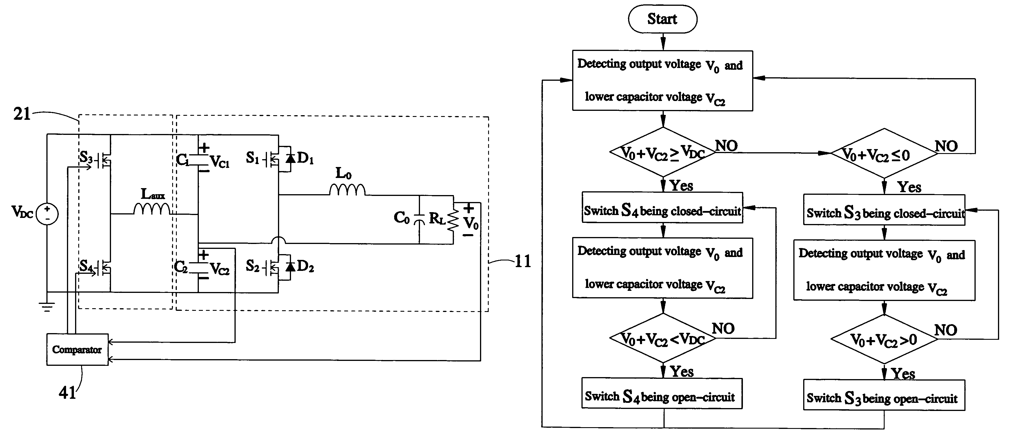
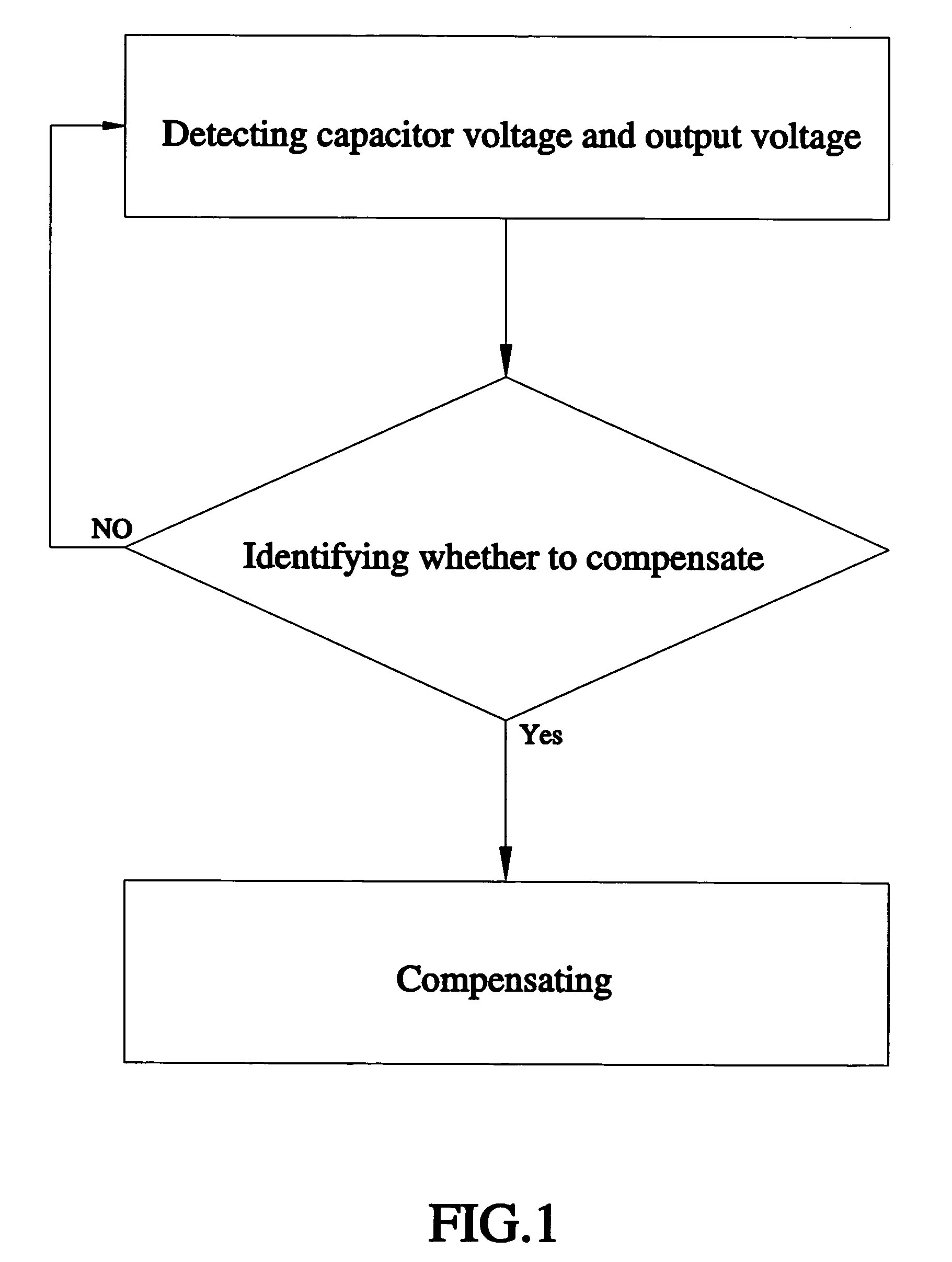
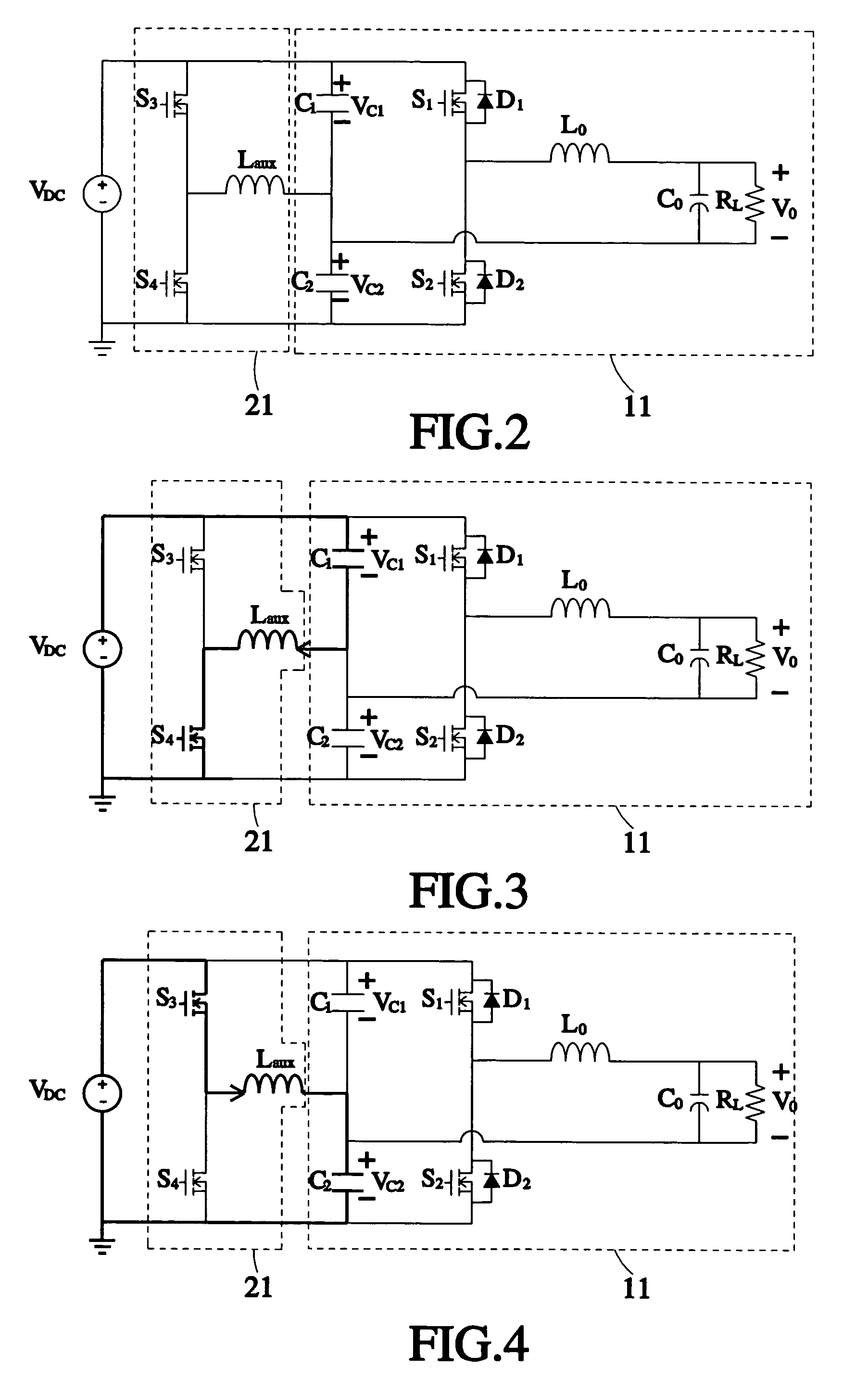
[0044]Referring to FIGS. 1-2, a method of compensating capacitor voltage unbalance of a half-bridge inverter, according to a preferred embodiment of the present invention, includes the following steps.

[0045]A. Detecting Capacitor Voltage and Output Voltage[0046]Measure a voltage of at least one capacitor of a half-bridge inverter 11 and detect an output voltage VO of the half-bridge inverter 11. In this embodiment, the half-bridge inverter 11 includes two capacitors, i.e. an upper capacitor C1 and a lower capacitor C2, one or two of which are for measurement and detection.

[0047]B. Identifying Whether to Compensate[0048]Compare the output voltage with the measured voltages VC1 and VC2 of the two capacitors C1 and C2 in the step A and identify the degree of distortion of the output voltage VO while the voltages VC1 and VC2 are unbalanced. If the degree of distortion matches a predetermined condition, the electric energy of the capacitors C1 and C2 will be too sufficient to provide a l...


PUM


Abstract

A method of compensating output voltage distortion of a half-bridge inverter and a device based on the method discloses that the method includes the steps of measuring the voltage of the capacitor of the half-bridge inverter and then detecting the output voltage of the same; comparing the capacitor voltage and the output voltage to identify how much degree the distortion is resulted from the capacitor voltage unbalance, wherein if the degree of the distortion matches a predetermined condition, proceed to the next step; and charging the capacitor through a compensating circuit to compensate the capacitor for the insufficient electric energy to enable the capacitor to provide the load with the sufficient electric energy. Thus, the drawback that the waveform of the output voltage can be improved to enable the device and the method to have advantages of simple circuit, easy control, reduced capacitance, and being applicable to any output frequency.

Description

BACKGROUND OF THE INVENTION[0001]1. Field of the Invention[0002]The present invention relates generally to electronic circuits, and more particularly, to a method of compensating output voltage distortion of a half-bridge inverter and a device based on the method.[0003]2. Description of the Related Art[0004]Referring to FIG. 9, a circuitry of a conventional half-bridge inverter includes a direct current (DC) voltage source VDC, an upper capacitor C1 and a lower capacitor C2, both of which are serially interconnected, two active switches S1 and S2, and an output end. The output end has a filter circuit composed of an inductor LO and a capacitor CO. A general half-bridge inverter is controlled by sinusoidal pulse width modulation and the two switches S1 and S2 are complementarily switchable.[0005]During the positive half cycle of the output voltage of the above-mentioned half-bridge inverter, there are two operational statuses as follows.[0006]1. The Switch S1 Being Closed-Circuit and...

Claims


Application Information

Patent Timeline
Patent Type & Authority Patents(United States)
IPC IPC(8): H02M3/335H02M7/44H02M7/68
CPCH02M7/538H02M2007/4811H02M7/4811
Inventor CHEN, YAOW-MINGWANG, WEI-CHENG
Owner NATIONAL CHUNG CHENG UNIV
Learn More