
Predictive failure analysis of thermal flying height control system and method

a control system and temperature control technology, applied in the field of data storage devices, can solve the problems of increasing error rates, affecting predictive modeling, and affecting the life of slider heaters,

Inactive Publication Date: 2008-02-26
WESTERN DIGITAL TECH INC
View PDF19 Cites 28 Cited by
  • Summary
  • Abstract
  • Description
  • Claims
  • Application Information

AI Technical Summary

Problems solved by technology

Heater failure can be catastrophic for drive operation, because it will result in the transducer flying height 404 to be even greater than the slider flying height hs, due to the cooling of the slider (FIG. 4).
At the greater transducer flying height, error rates will increase significantly due to the high areal densities of the stored data.
This degree of complexity is not useful for the prediction of slider heater lifetimes, due to the difficulty of obtaining detailed heater element temperature data within the slider.
The predictive modeling is made more difficult due to the convective cooling experienced by a slider over moving media.
This method is unsuitable for application in disk drive slider heaters since the failure warning must be provided well before the “burn out” or open circuit state of the heater is reached.
Possible future failure of the disk drive is predicted as a function of any changes in these two electrical parameters, as these parameters may change over a period of time; i.e., may change over a number of disk drive stop / start events.
However, this only provides information while the circuit is in the process of operating.
If the error diagnostic register contains single polarity voltage baseline jumps, the voltage baseline jumps may be caused by thermal asperities on the disk.
If the error diagnostic register contains both positive and negative voltage baseline jumps, the voltage baseline jumps may be caused by MR head instability.

Method used


Image

  • Predictive failure analysis of thermal flying height control system and method
  • Predictive failure analysis of thermal flying height control system and method
  • Predictive failure analysis of thermal flying height control system and method

Examples


Embodiment Construction

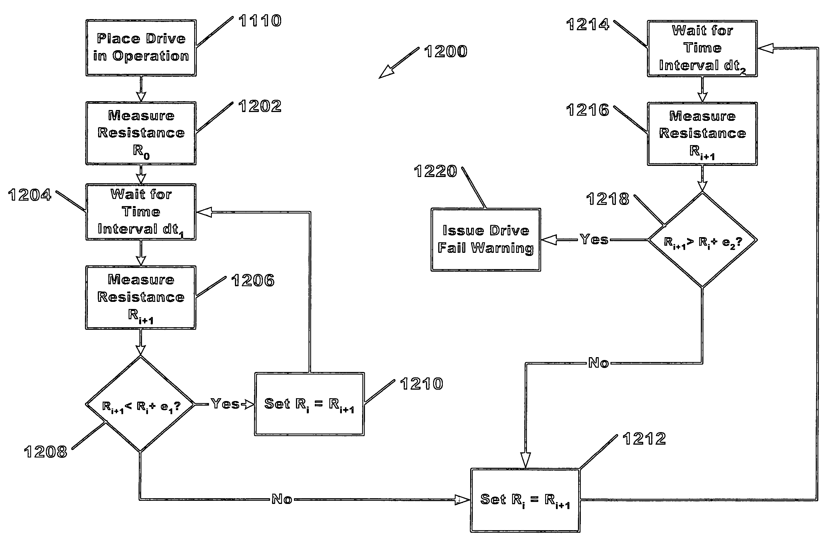
[0046]At the high areal densities of today's modern data storage drives, the transducer to media dimensions are critical, and are usually required to be below the slider flying heights. This is accomplished by heating the transducer containing portion of the slider, as previously discussed above. To extend the long term reliability of the drives, monitoring of the heater performance has become desirable. In commercial industrial heating applications, the failure of wire-wound and cartridge type heaters has also been a concern, and the prediction of heater failure has been the subject of significant prior art. However, this prior art is of little use to designers and those skilled in the art of data storage devices. The reason being that failure of industrial heaters is usually defined as “burn out” condition or rupture of the heating element causing an open circuit condition. In data drive applications, heater failure is considerably more critical, in that for a failure warning to b...


PUM

PropertyMeasurementUnit
timeaaaaaaaaaa
timeaaaaaaaaaa
time periodaaaaaaaaaa

Abstract

A method for predicting the failure of a data storage device having a slider heater is disclosed. For slider heaters exhibiting a decreasing resistance aging characteristic, a failure warning is produced when heater resistance suddenly increases 2 to 5%, or dR / dt changes sign from negative to positive. For slider heaters exhibiting an increasing resistance aging characteristic, a failure warning is produced when the heater resistance suddenly drops 2 to 5%, or dR / dt changes sign from positive to negative. Additionally, random changes in heater resistance exceeding nominal measurement error may also be utilized to produce a failure warning. This method provides advance warning of potential data read / write errors well before the open circuit failure of the slider heater occurs.

Description

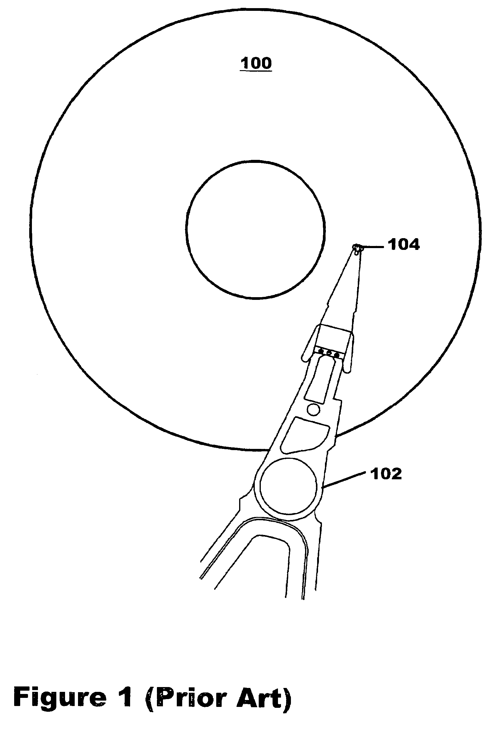
BACKGROUND OF THE INVENTION[0001]1. Field of the Invention[0002]The present invention relates to data storage devices that employ aerodynamically supported transducing sliders for reading and recording magnetic data, and more particularly to the prediction of failure of heating devices resident within the transducing sliders.[0003]2. Description of the Related Art[0004]A magnetic direct access storage device or disk drive contains at least one rotating disk covered with a magnetic coating which can store electronic data, and an apparatus for reading data from and writing data to that disk. This is implemented by a motor to rotate the disk, a transducer to read and write data to and from the disk, an actuator arm to position the transducer over the disk surface, and associated electronic circuitry to transfer information between the transducer and an accessing source. A typical configuration is shown in FIG. 1 (Prior Art). Data stored on the surface of magnetic disk 100 is accessed b...

Claims


Application Information

Patent Timeline
Patent Type & Authority Patents(United States)
IPC IPC(8): G11B5/00G11B27/36G11B21/02
CPCG11B5/40G11B20/18G11B2220/2516
Inventor LILLE, JEFFREY S.SUK, MIKE
Owner WESTERN DIGITAL TECH INC
Learn More