
Bus powered wireless transmitter

a wireless transmitter and bus technology, applied in the field of process control transmitters, can solve the problems of limited access to device diagnostics, low savings from wiring using the hart® protocol, and large amount of cabling cost in the home run cable, and achieve the effect of facilitating communication

Active Publication Date: 2008-02-12
ROSEMOUNT INC
View PDF27 Cites 47 Cited by
  • Summary
  • Abstract
  • Description
  • Claims
  • Application Information

AI Technical Summary

Benefits of technology

This approach reduces cabling costs, simplifies power regulation, and allows for dynamic deployment of field devices, enabling flexible network configurations and cost-effective expansion without the need for expensive homerun cabling, while supporting higher data rates and longer transmission distances.

Problems solved by technology

Since cabling distances from the field device to the junction box are relatively short, the bulk of the cabling cost is in the home run cable.
HART® is a well established standard but control systems in general do not support HART® multidrop configurations; therefore, there is little savings from wiring using the HART® protocol.
The few control systems supporting HART® generally have limited access to device diagnostics and do not use the digital information for control due to speed limitations.
Using the same pair of wires for communication and power also makes power regulation of the device more complicated.
Simple low pass filters cannot be used to remove noise from the power signal because a “notch” at the communications frequency must be allowed to pass.
However, power constraints of wireless transmitters typically limit process control networks to the traditional wired topology.
However, such wireless transmitters suffer from the basic problem of low available power, which tends to limit the utility of such field devices.
Specifically, the low available power forces the use of low data rates to help conserve energy, and / or requires frequent, periodic replacement of the power source.

Method used


Image

  • Bus powered wireless transmitter
  • Bus powered wireless transmitter
  • Bus powered wireless transmitter

Examples


Embodiment Construction

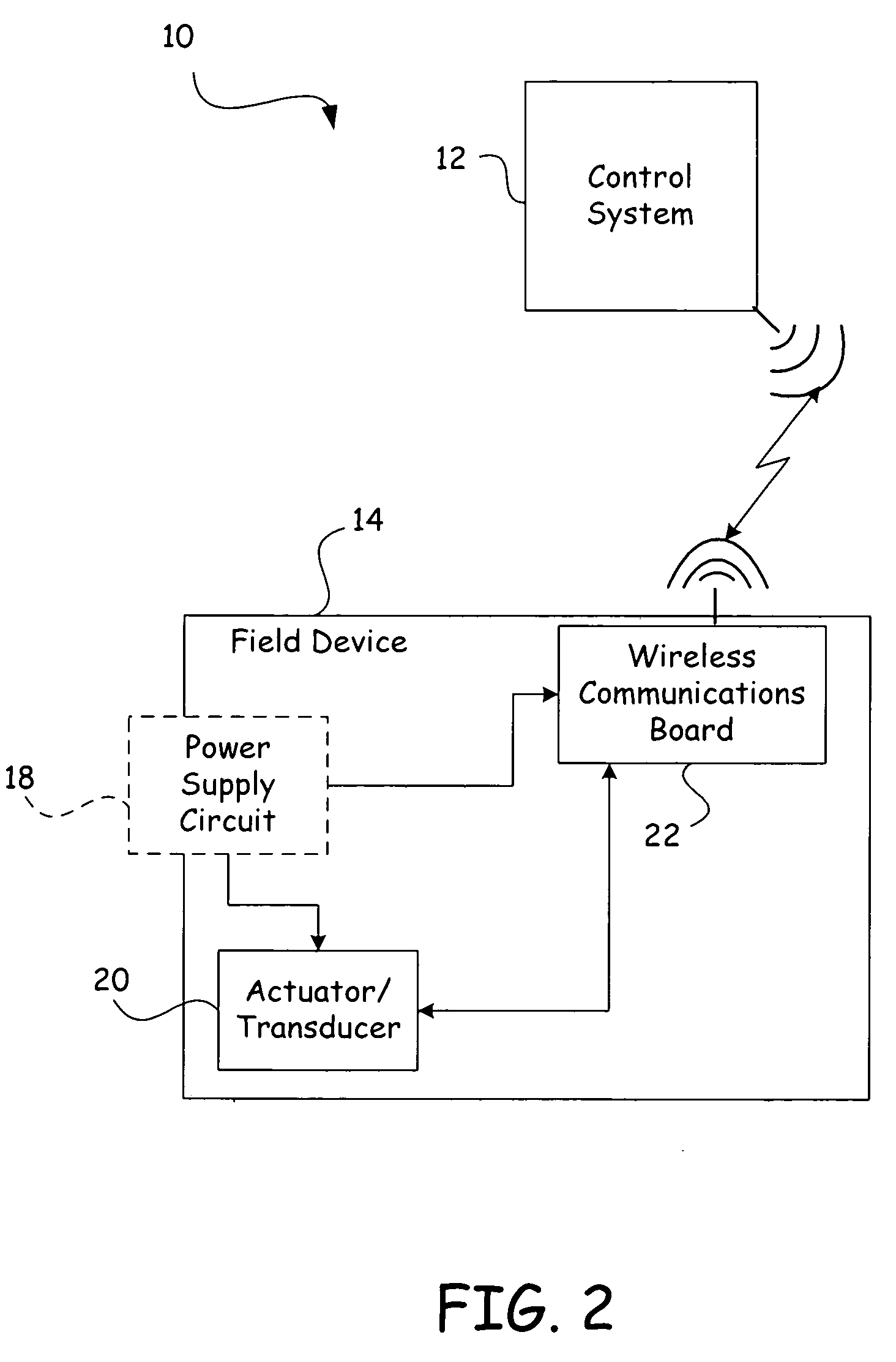
[0018]The present invention takes advantage of available wireless technologies to free the process control network from its traditional wired topologies. Wireless transceivers can be used both to adapt existing process control networks to provide wireless communications capabilities and to construct process control networks without costly homerun cabling and without expensive power filters.

[0019]In general, the wireless transceivers send and receive data wirelessly, thereby divorcing the signaling or communications path from the physical wiring. While conventional process control networks provided power and signaling over the same set of wires, by handling the power supply to the field devices separately from the signaling or communications path in the present invention, the field devices are no longer bound to the physical wiring of a control network. Instead, data is transmitted wirelessly, and power is supplied to the field devices from a variety of different means, allowing the ...


PUM


Abstract

A process control system utilizes wireless transceivers to divorce the field devices from traditional wired network topologies. By providing field devices with wireless transceivers and shared wireless transceivers for adapting wired field devices, the field device network may be adapted to any number of network topologies without concern for additional wiring costs. Specifically, a power supply can be provided for each field device or for groups of field devices, as needed. Thus, the entire network can receive power from a single power bus, without expensive power filtering. In addition, the network can be a hybrid in which part of the information is transmitted and received over wired lines and part is transmitted and received over wireless communications.

Description

BACKGROUND OF THE INVENTION[0001]The present invention relates to process control transmitters used to measure process variables in industrial processing plants. More particularly, the present invention relates to field devices with wireless transceivers powered by an external common DC bus for power supply or by an existing power circuit.[0002]In industrial settings, control systems monitor and control inventories, industrial and chemical processes, and the like. Typically, the control system perform these functions using field devices distributed at key locations in the industrial process and coupled to the control circuitry in the control room by a process control loop. The term “field device” refers to any device that performs a function in a distributed control system, including all devices currently known in the measurement and control art.[0003]Generally, each field device includes a transducer. A transducer is understood to mean either a device that generates an output signa...

Claims


Application Information

Patent Timeline
Patent Type & Authority Patents(United States)
IPC IPC(8): H04B7/00H04W88/02
CPCH04W88/02G05B19/41855G05B2219/31251H02J50/80H02J7/00034H02J13/00028Y02P90/02
Inventor KARSCHNIA, ROBERT J.PELUSO, MARCOSROMO, MARK G.
Owner ROSEMOUNT INC
Learn More