
Apparatus and method for degrading a web in the machine direction while preserving cross-machine direction strength

a technology of machine direction and applicator, applied in the direction of manufacturing tools, applications, ways, etc., to achieve the effect of reducing the tensile ratio of the web

Inactive Publication Date: 2008-02-05
GPCP IP HLDG LLC
View PDF49 Cites 52 Cited by
  • Summary
  • Abstract
  • Description
  • Claims
  • Application Information

AI Technical Summary

Benefits of technology

The invention is an embossing system for embossing and perforating a web. The system includes two embossing rolls with embossing elements that produce perforating nips when juxtaposable. The cross-machine direction elements on the rolls are angled to create a non-picking clearance and reduce the machine direction tensile strength of the web. The system also includes a method for reducing the tensile ratio of the web by embossing and perforating it. The technical effects of the invention include improved embossing and perforating capabilities, reduced picking, and improved quality of the finished product.

Problems solved by technology

Picking can result from drift caused by local variances in roll diameter or gearing from the ideal.

Method used


Image

  • Apparatus and method for degrading a web in the machine direction while preserving cross-machine direction strength
  • Apparatus and method for degrading a web in the machine direction while preserving cross-machine direction strength
  • Apparatus and method for degrading a web in the machine direction while preserving cross-machine direction strength

Examples


examples

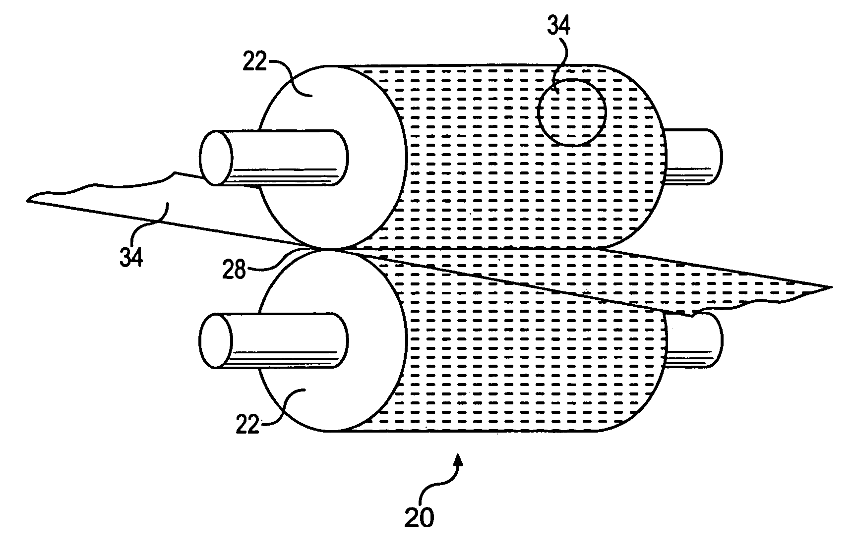
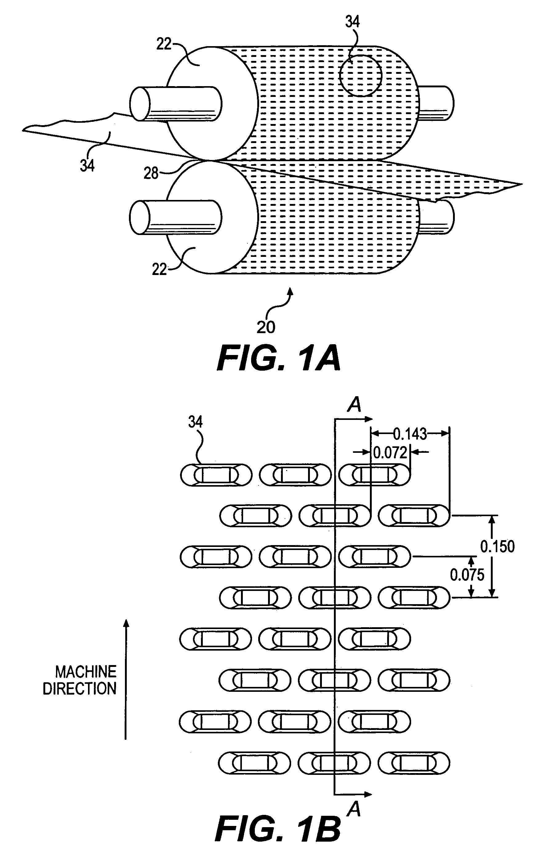
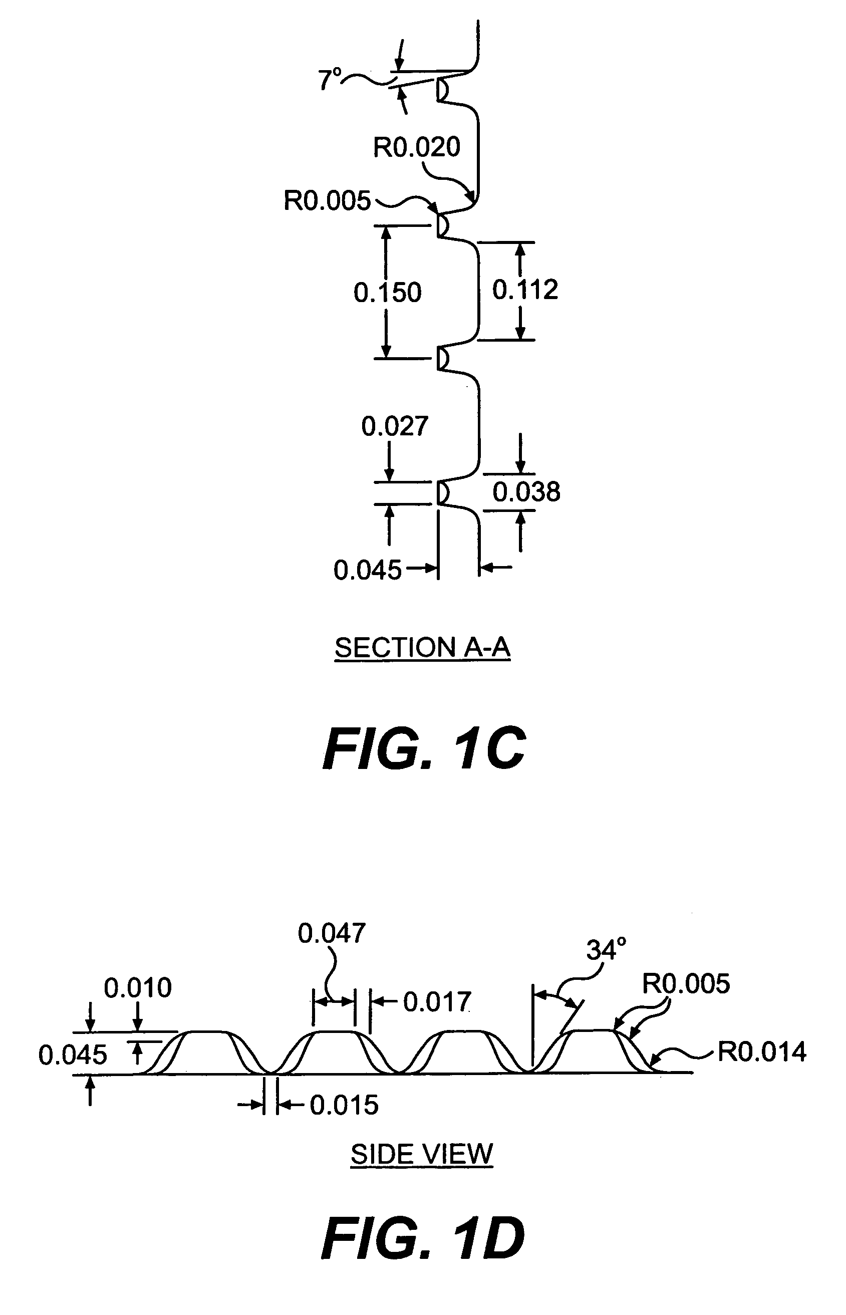
[0086]The following examples exhibit the occurrence of picking observed in certain arrangements of cross-machine direction perforate embossed patterns. This data was generated during trials using steel embossing rolls engraved with the cross-machine direction beveled oval embossing pattern at three different sidewall angles. In particular, the embossing rolls were engraved with three separate regions on the rolls—a 7° embossing pattern, a 9° embossing pattern, and an 11° embossing pattern. Two trials were performed. In the first trial, the embossing rolls had an element height of 45 mils. The base sheet, having a thickness of 6.4 mils, was embossed at engagements of 16, 24, and 32 mils. In the second trial, the steel rolls were modified by grinding 2.5 mils off the tops of the embossing elements, thereby reducing the element height to 42.5 mils and increasing the surface area of the element tops. The base sheet having a thickness of 6.2 mils was embossed at engagements of 16, 24, 28...


PUM

PropertyMeasurementUnit
transmittivityaaaaaaaaaa
angleaaaaaaaaaa
angleaaaaaaaaaa

Abstract

An embossing system is provided for embossing a web having a first embossing roll having embossing elements and a second embossing roll having embossing elements, wherein at least a portion of the embossing elements of the first and second embossing rolls are substantially oriented in the cross-machine direction. The embossing roll may be crowned, may have alignment means, and may be provided with precision gearing.

Description

CONTINUING DATA[0001]This is a divisional of application Ser. No. 10 / 236,993, filed Sep. 5, 2002 (now U.S. Pat. No. 6,887,349), which is a continuation-in-part of application Ser. No. 10 / 036,770, filed Dec. 21, 2001 (now U.S. Pat. No. 6,733,626), both of which are incorporated herein by reference in their entireties.[0002]The present invention relates to an apparatus and method for embossing a moving web of material, such as paper, to create a functional controlled degradation of the machine direction strength of the web while limiting degradation of the cross-machine direction strength of the web. In one embodiment, the present invention relates to an apparatus and method for embossing a moving web using an embossing system having perforate embossing elements oriented to define perforating nips substantially oriented in the cross-machine direction to improve the flexibility, feel, bulk, and absorbency of the paper. In another embodiment, the present invention relates to an apparatu...

Claims


Application Information

Patent Timeline
Patent Type & Authority Patents(United States)
IPC IPC(8): D21F11/00B31F1/07A61F13/15
CPCA61F13/15731B31F1/07B31F2201/0728B31F2201/0735B31F2201/0738B31F2201/0743B31F2201/0753B31F2201/0756B31F2201/0779B31F2201/0797
Inventor RUTHVEN, PAUL J.GRACYALNY, DALE T.SCHULZ, GALYN A.DEMILLE, JOHN R.MOGGED, III, OTTOKRASZEWSKI, ALAN J.WILLIAMS, ROBERT J.ZAHN, HARLIE C.DAUS, ROBERT R.HANSEN, MARK D.
Owner GPCP IP HLDG LLC
Learn More