
Hydrogen-oxygen gas generator and hydrogen-oxygen gas generating method using the generator

a hydrogen gas and generator technology, applied in electrolysis, refrigeration machines, refrigeration components, etc., can solve the problems of limited efficiency of apparatus and methods of the related art, possible distance between adjacent electrodes, and inability to achieve the effect of generating hydrogen gas and oxygen gas for industrial use, and achieve satisfactory uniformity, high efficiency, and high efficiency

Active Publication Date: 2008-01-15
JAPAN TECH CO LTD (JP)
View PDF7 Cites 37 Cited by
  • Summary
  • Abstract
  • Description
  • Claims
  • Application Information

AI Technical Summary

Benefits of technology

"The present invention provides a hydrogen-oxygen gas generator comprising an electrolytic cell and an electrolysis means. The generator also includes a vibration-stirring means for stirring and agitating the electrolyte fluid within the cell. The vibration-stirring means includes a vibration generating means and a vibrating rod with vibrating blades attached to it. The vibration blades are designed to vibrate within the cell. The generator also includes a gas trapping means for collecting the hydrogen gas and oxygen gas generated by electrolysis. The vibration generating means can be a frequency of 10 to 500 Hz. The invention provides an improved method for generating hydrogen-oxygen gas through electrolysis."

Problems solved by technology

However, no method up until now has succeeded in generating a gas mixture of hydrogen gas and oxygen gas for industrial use.
However, in this method of the related art, the shortest possible distance between the adjacent electrode plates within this kind of electrolytic cell was a gap of 50 millimeters just sufficient to prevent electrical shorts.
An even shorter distance between electrode plates tended to cause accidents due to excessive current flow.
The efficiency of the apparatus and method of the related art was therefore limited when producing hydrogen-oxygen gas by increasing the electrical current density.
The related art therefore had the problem that it could not generate gas with high efficiency.
The related art also could not provide an adequate mixture of hydrogen and oxygen, creating the danger of the gas igniting and was not therefore suited for producing gas in large quantities.
On the other hand, since the size of each electrolytic cell was limited, the amount of hydrogen-oxygen gas produced by one hydrogen-oxygen gas generator was also limited.
However, the apparatus of the related art could not satisfy the dual needs of both a compact size and generation of larger amounts of hydrogen-oxygen gas.

Method used


Image

  • Hydrogen-oxygen gas generator and hydrogen-oxygen gas generating method using the generator
  • Hydrogen-oxygen gas generator and hydrogen-oxygen gas generating method using the generator
  • Hydrogen-oxygen gas generator and hydrogen-oxygen gas generating method using the generator

Examples


first embodiment

[0204]Utilizing the device as described in FIG. 40 and FIG. 41, hydrogen-oxygen gas was generated and collected under the following conditions.

Electrolytic Cell:

[0205]Manufactured from (SUS304) stainless steel (2 mm thick inner surface of heat-resistant polyvinyl plastic) 740 mm×2100 mm×700 mm (H)

Lid Member:

[0206]Manufactured from (SUS304) stainless steel, insulated vibration stirring means employs the sealed structure of FIG. 4 and FIG. 5.

Insulated Vibration Stirring Means:

[0207]Vibration motor; Uses inverter manufactured by Murakami Seiki Seisakusho (Corp.) (product name), 400W×3-phase×200 V, 6 unit operating at 40 Hz.[0208]Vibrating blades: Manufactured from titanium, 6 blades[0209]Affixed with the polyethylene tape as shown in FIG. 34.[0210]Interelectrode gap: A gap of 20 millimeters was set among adjacent electrode support blades of both of the insulated vibration stirring means.[0211]Electrolytic fluid: KOH added as electrolytic material at 8 percent by weight to distilled wat...

second embodiment

[0218]Utilizing the device as described in FIG. 37 through FIG. 39, hydrogen-oxygen gas was generated and collected under the following conditions.

Electrolytic Cell:

[0219]Manufactured from (SUS304) stainless steel (inner surface of heat-resistant polyvinyl plastic sheath plastizol finishing)

[0220]400 mm×700 mm×550 mm(H)

Lid Member:

[0221]Manufactured from (SUS304) stainless steel, insulated vibration stirring means employs the sealed structure of FIG. 4 and FIG. 5.

Insulated Vibration Stirring Means:

[0222]Vibration motor; Uses inverter manufactured by Murakami Seiki Seisakusho (Corp.) (product name), 150 W×3-phase×200 V, 2-axis type, 2 units with inverter operated at 40 Hz.[0223]Vibrating blades: Manufactured from titanium, 6 blades. Dimension D2 of FIG. 33 is 55 millimeters.[0224]Electrode support blades: Manufactured from titanium, 2 blades (Used only on highest section and lowest section.)[0225]Dimension D2 of FIG. 33 is 150 millimeters.[0226]Anode member & cathode member: Titanium ...

third embodiment

[0236]Utilizing the device as described in FIG. 24 through FIG. 26, hydrogen-oxygen gas was generated and collected under the following conditions.

Electrolytic Cell:

[0237]Manufactured from stainless steel (2 mm thick inner surface of heat-resistant polyvinyl plastic) 740 mm×2100 mm×700 mm (H)

Lid Member:

[0238]Manufactured from (SUS304) stainless steel, insulated vibration stirring means employs the sealed structure of FIG. 4 and FIG. 5.

Insulated Vibration Stirring Means:

[0239]Vibration motor; Uses inverter manufactured by Murakami Seiki Seisakusho (Corp.) (product name), 400 W×3-phase×200 V, 6 units operating at 40 Hz.[0240]Vibrating blades: Manufactured from titanium (usable for both anode member or cathode member), 6 blades[0241]Anode member & cathode member: Cylindrical titanium mesh case of FIG. 53 with overlapping electrodes[0242]Electrolytic fluid: KOH added as electrolytic material at 25 percent by weight to distilled water, temperature 55° C.,[0243]Voltage applied across cath...


PUM

PropertyMeasurementUnit
frequencyaaaaaaaaaa
pHaaaaaaaaaa
temperatureaaaaaaaaaa

Abstract

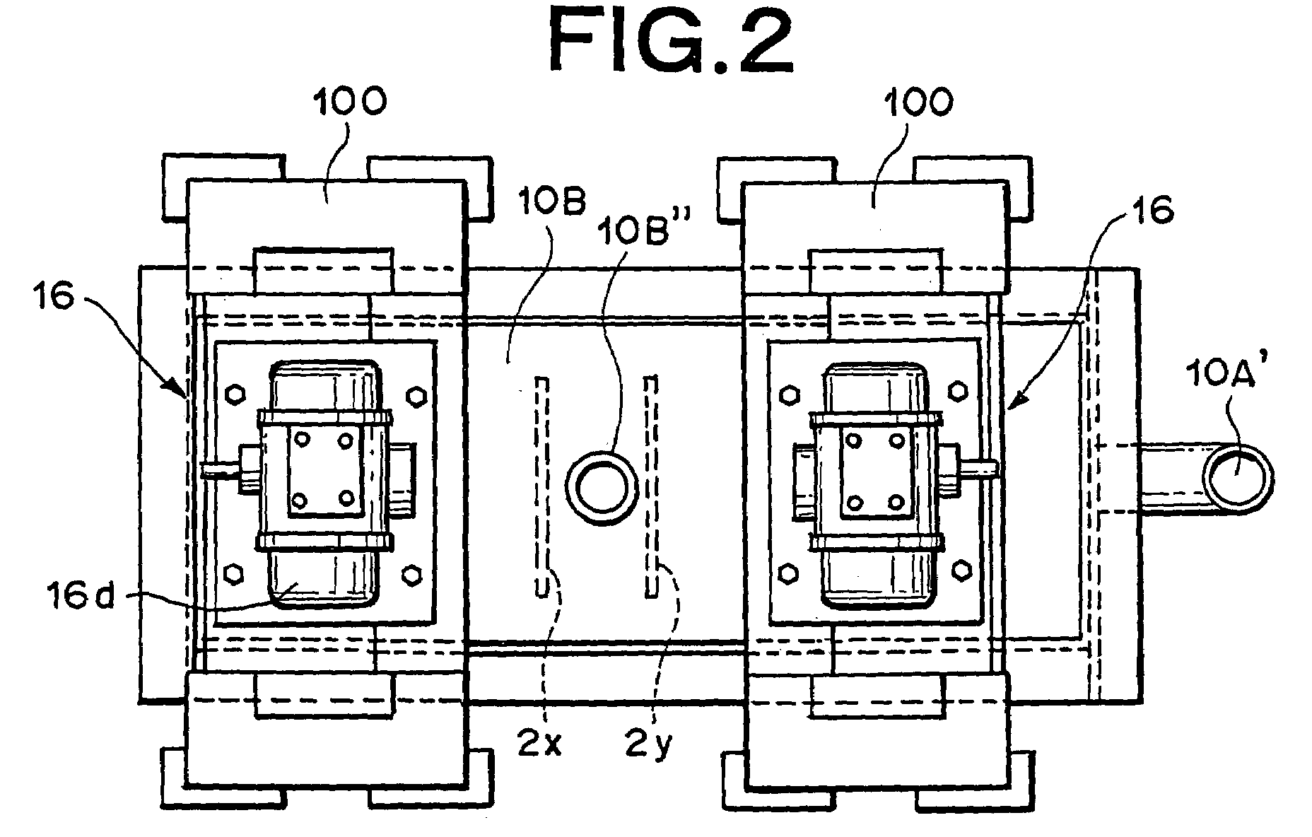
A hydrogen-oxygen gas generator comprises an electrolytic bath (10A), a pair of electrodes composed of an anode member (2x) and cathode member (2y) both disposed in the bath, a power supply (34) for applying voltage between the anode and cathode members, vibratory mixing means (16) for vibratively mixing the electrolyte (14) in the bath, and gas collecting means for collecting the hydrogen-oxygen gas generated by the electrolysis using the electrolyte. The gas collecting means includes a lid member (10B) annexed to the electrolytic bath (10A) and a hydrogen-oxygen gas collecting pipe (10B″) connected to the hydrogen-oxygen gas output port (10B′). The vibratory mixing means (16) includes a vibrating motor (16d) vibrating at 10 Hz to 500 Hz and vibrating blades (16f) attached to a vibrating rod (16e) not rotatably but vibrating in the electrolytic bath interlockingly with the vibrating motor. The vibrating blades of the vibratory mixing member (16) are so arranged as to oppose the surfaces of the anode and cathode members (2x, 2y).

Description

[0001]This application is a 371 of PCT / JP02 / 09770 filed on Sep. 24, 2002, published on Jun. 12, 2003 under publication number WO 03 / 048424 A1 which claims priority benefits from Japanese Patent Application Number 2001-369297 filed Dec. 3, 2001.BACKGROUND OF THE INVENTION[0002]1. Field of the Invention[0003]The present invention relates to an apparatus and method for generating hydrogen-oxygen gas by electrolysis, and relates in particular to an hydrogen-oxygen gas generator and hydrogen-oxygen gas generating method for generating hydrogen gas and oxygen gas with high efficiency and collecting the hydrogen and oxygen gas separately or as a gas mixture to generate a gas with a high flame temperature.[0004]2. Description of the Related Art[0005]Electrolysis or electrolytic technology was pioneered by the scientist Faraday. The electrolysis of water is known to produce hydrogen-oxygen gas in a ratio of two parts hydrogen to one part oxygen. Research on hydrogen-oxygen gas has continued ...

Claims


Application Information

Patent Timeline
Patent Type & Authority Patents(United States)
IPC IPC(8): C25B9/12C25B9/17C25B15/00
CPCC25B1/04C25B9/06C25B15/00Y02E60/366Y02E60/36C25B9/17
Inventor OMASA, RYUSHIN
Owner JAPAN TECH CO LTD (JP)
Learn More