
Two-layer drum cover made of a metal alloy in the warp directions and a plurality of metal alloys in the shute directions on both front and back surfaces

a drum cover and warp direction technology, applied in the field of slurry preparation, can solve problems such as failure of drum wires, and achieve the effects of reducing the frequency of drum cover replacement, and reducing the corrosion of face wires

Active Publication Date: 2008-01-15
ALBANY INT CORP
View PDF8 Cites 0 Cited by
  • Summary
  • Abstract
  • Description
  • Claims
  • Application Information

AI Technical Summary

Benefits of technology

The sacrificial anode design significantly increases the drum life and reduces the frequency of replacement by allowing corrosion to occur in the non-load bearing members first, thereby protecting the load bearing members and extending the overall life of the drum cover.

Problems solved by technology

In particular, the inventors have noted that due to the highly corrosive environment during use, the backing wire and face wire tend to corrode leading to the failure of the drum wires.

Method used


Image

  • Two-layer drum cover made of a metal alloy in the warp directions and a plurality of metal alloys in the shute directions on both front and back surfaces
  • Two-layer drum cover made of a metal alloy in the warp directions and a plurality of metal alloys in the shute directions on both front and back surfaces
  • Two-layer drum cover made of a metal alloy in the warp directions and a plurality of metal alloys in the shute directions on both front and back surfaces

Examples


Embodiment Construction

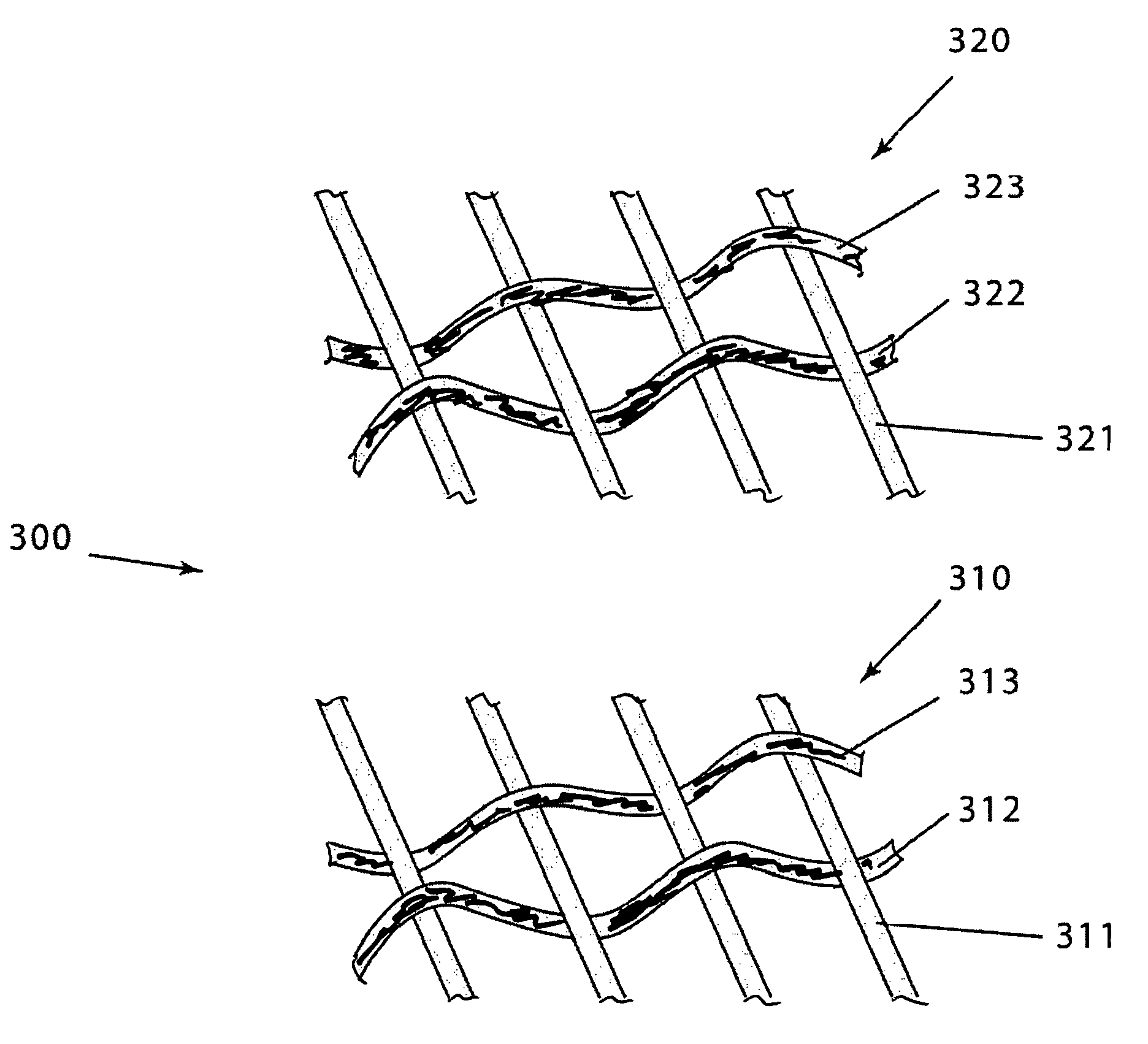
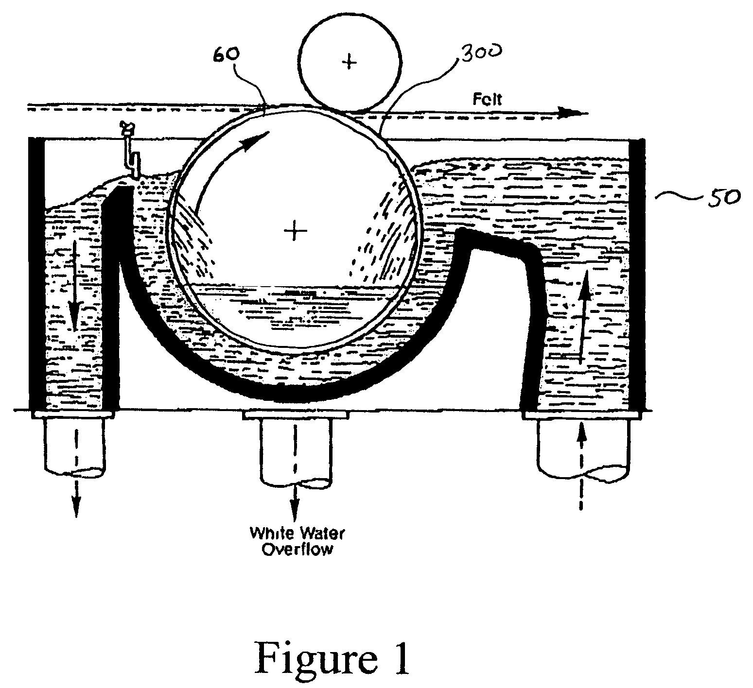
[0032]FIG. 1 depicts a cross sectional view of a cylinder 50 including a drum 60. FIG. 5 depicts a cross sectional view of washing zone 100 including a drum 200. A two-layer drum cover 300 protects drum 60 in cylinder 50 (see FIG. 1) and drum 200 in washing zone 100 (see FIG. 5). The two-layer drum cover 300 is constructed of a backing wire 310 and a face wire 320 (see FIG. 6).

[0033]The two-layer drum cover is designed according to the “sacrificial anode” principle. In sacrificial anode designs, the non-load bearing members of both the backing wire 310 and face wire 320 are constructed of lower grade metal alloys than the respective load bearing members. As such, the non-load bearing members act as sacrificial anodes for the load bearing members in their respective wires. Further, the backing wire 310 acts as a sacrificial anode to protect the face wire 320. Due to such arrangement, corrosion occurs in the following sequence:[0034]1. Non-load bearing lower grade members of the backi...


PUM

PropertyMeasurementUnit
pHaaaaaaaaaa
durabilityaaaaaaaaaa
non-combustibleaaaaaaaaaa

Abstract

A two-layer drum cover and a method of producing the same are provided. The two-layer drum cover includes a backing wire constructed of a relatively high grade metal alloy in the warp direction and alternating relatively low grade metal alloys in the shute direction. The two-layer drum cover also includes a face wire constructed of a relatively high grade metal alloy in the warp direction and alternating relatively low grade metal alloys in the shute direction. All the metal alloys used in the face wire have a higher grade than the metal alloys used in the backing wire.

Description

FIELD OF THE INVENTION[0001]The present invention is directed towards the preparation of slurry for use in fibrous material production, and more particularly, towards the preparation of slurry to be used in the production of fibrous materials such as fiber cement or paper.BACKGROUND OF THE INVENTION[0002]Fiber cement is commonly used as siding in the housing industry due to the many advantages it provides. For instance fiber cement does not rot or deteriorate and therefore, provides long-term durability. Further, fiber cement is non-combustible.[0003]The production of fiber cement begins with a mixture of a special type of cement, silica, and fibers. Although asbestos fibers were once used in the production of fiber cement, now plastic fibers, carbon fibers, and wood fibers are more commonly found in fiber cement. The mixture is approximately 80% cement and silica and 20% fiber. The fibers act in a manner similar to reinforcing rods used in concrete.[0004]Water is added to the cemen...

Claims


Application Information

Patent Timeline
Patent Type & Authority Patents(United States)
IPC IPC(8): B05C11/00D03D15/00B01D33/00B01D39/12D21F1/10D21F1/60
CPCB01D33/0093B01D33/067Y10T29/49838Y10T428/13B01D33/465Y10T442/3228Y10T442/313
Inventor LEVINE, MARK J.ISRAEL, THOMAS L.ZILKER, GREGORY D.
Owner ALBANY INT CORP
Learn More