
System and method for X-ray spot control

a spot control and x-ray technology, applied in the field of x-ray imaging systems, can solve the problems of slow response time, insufficient quality of images, and large size of magnetic field systems, and achieve the effects of convenient and quick focus, compact reliability, and cost-effectiveness

Inactive Publication Date: 2008-01-08
GENERAL ELECTRIC CO
View PDF5 Cites 7 Cited by
  • Summary
  • Abstract
  • Description
  • Claims
  • Application Information

AI Technical Summary

Problems solved by technology

However, controlling the electron beams of such systems typically requires use of magnetic fields to divert and focus the e-beam as desired.
Unfortunately, forces produced by magnetic fields may have slow response times in manipulating the e-beam, which may be insufficient to produce images with desired quality.
Further, systems employing magnetic fields tend to be big in size and high in cost rendering them less desirable for vendors to purchase.

Method used


Image

  • System and method for X-ray spot control
  • System and method for X-ray spot control
  • System and method for X-ray spot control

Examples


Embodiment Construction

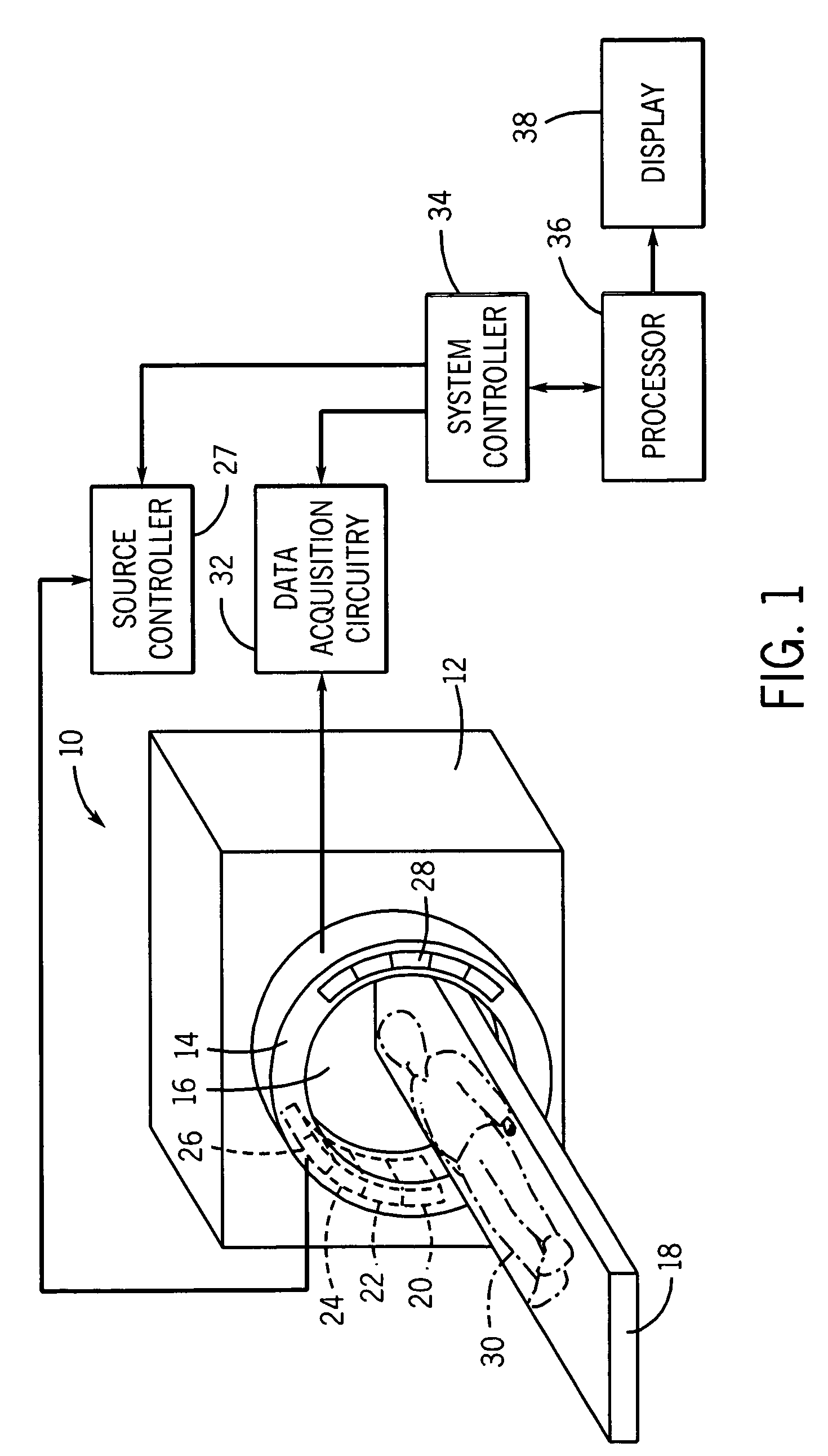
[0018]Referring generally to FIG. 1, an exemplary imaging system utilized in one present embodiment may be a CT scanning system 10. The CT scanning system 10 may be a multi-slice detector CT system that offers a wide array of axial coverage and high spatial resolution. The CT scanning system 10 is illustrated with a frame 12 and a gantry 14 that has an aperture 16. Further, a table 18 is illustrated positioned in the aperture 16 of frame 12 and gantry 14. Additionally, table 18 is configured to be displaced linearly by a positioning system. Gantry 14 is illustrated with multiple stationary radiation sources or X-ray tubes 20-26, each positioned and collimated to emit X-ray radiation along axial and angular directions. The X-ray tubes 20-26 are coupled to an X-ray tube source controller 27, configured to control the operation of each of X-ray tubes 20-26. Disposed 180 degrees opposed to the X-ray tubes are stationary detectors 28, generally formed by a plurality of detector elements,...


PUM


Abstract

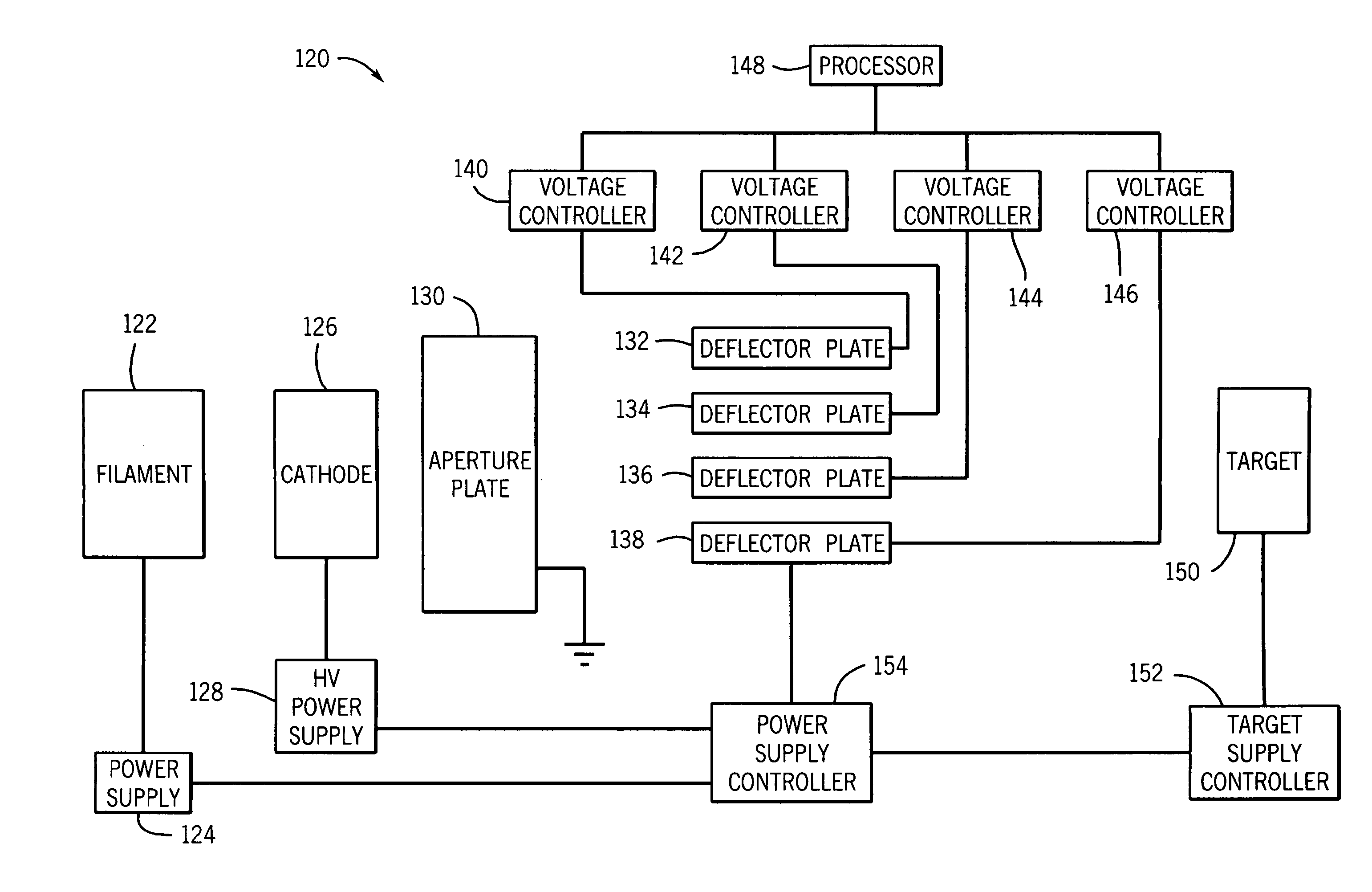
The present technique provides a method for controlling an electron beam (e-beam) in an X-ray tube. The method comprises emitting electrons from an electron source to form the e-beam, accelerating the e-beam from a cathode through an aperture in a plate, focusing and steering the e-beam from the aperture through a plurality of field generating plates, and accelerating the e-beam from the plurality of the field generating plates to a target. Also provided are X-ray tubes and computed tomography systems.

Description

STATEMENT REGARDING FEDERALLY SPONSORED RESEARCH AND DEVELOPMENT[0001]This invention was made with Government support under contract number HSTS04-04-G-RED940 awarded by Transportation Security Administration. The Government has certain rights in the invention.BACKGROUND[0002]The present invention generally relates to the field of X-ray imaging systems such as computed tomography (CT) systems and more particularly to a method and apparatus for focusing and bending of electron beams in an X-ray tube.[0003]X-ray imaging systems, such as CT systems, operate by projecting fan shaped or cone shaped X-ray beams through an object. The X-ray beams are generated by an X-ray source, and are generally collimated prior to passing through the object being scanned. The attenuated beams are then detected by a set of detector elements. The detector elements produce a signal based on the intensity of the attenuated X-ray beams, and the signals are processed to produce projection or tomographic image...

Claims


Application Information

Patent Timeline
Patent Type & Authority Patents(United States)
IPC IPC(8): H01J35/30
CPCH01J35/04H01J35/14H01J35/30H01J2235/06H01J35/153H01J35/147
Inventor ZOU, YUNCAO, YANGVERMILYEA, MARK ERNEST
Owner GENERAL ELECTRIC CO
Learn More