Alignment of clock domains in packet networks

a clock domain and packet network technology, applied in the field of digital communications, can solve the problems of network creation of different problems, inability to meet all telecommunication standards, and inability to use a shared clock, and achieve the effect of extra cos

Active Publication Date: 2008-01-01
ZARLINK SEMICON LTD
View PDF21 Cites 34 Cited by
  • Summary
  • Abstract
  • Description
  • Claims
  • Application Information

AI Technical Summary

Benefits of technology

[0022]The invention relates the various clocks to shared events on the network with proper processing to avoid misinterpretation of the observed behaviors and take into account possible network delays. The resulting performance can be shown to be superior due to elimination of a few error effects. Thus the invention can serve as an improvement over ACR, which in turn makes methods, such as RTS, with its associated extra cost, unnecessary.

Problems solved by technology

The use of a shared clock is not attractive due to the associated costs for a GPS receiver or wiring, including connectors and the like.
The current performance of ACR is not sufficient to meet all telecommunication standards, which typically require absolute time stabilities in the order of 50-20 ns.
Different network topologies and different uses of a network create different problems.
Current methods do not meet these requirements for various reasons.
For example, in ACR, the variability of the delay of packets is a problem, independent of the method employed.
The problem with such an approach is that the delays can be modeled essentially as a stochastic process.
Averaging of the packet arrival rate as input for some time recovery mechanism, such as a PLL, does work, but is very slow, as is known from standard signal theory.
A time constant of 10,000 seconds requires very expensive crystal oscillators or even atomic resonators (the cheapest crystal oscillators start to have problems around 1-10 seconds), which is prohibitive for the solution both in required lock time and cost of the solution.
Simply increasing the packet transfer rate is not feasible, as the bandwidth overhead for timing purposes only should remain restricted to a few percent.
Increasing this rate by a factor 10 would decrease the effective low pass frequency by a factor 10, which is still far from the range of cheap crystals, but already uses up a lot of network bandwidth.
The plesiochronous solution is not satisfactory.
This solution accepts the fact that there will be ‘slips’, and tries to minimize the frequency of such slips, typically by employing expensive, high accuracy clocks.
Accepting slips can be acceptable for voice applications, but for synchronous data applications it can become quite disastrous.
If combinations of specific forms of security are associated with the traffic (such as stream ciphering), a slip may result in the loss of a session altogether.
In modern networks, where many types of service are intermingled, such solutions are not acceptable.
At the same time, the associated cost for the extra wiring or (backplane) antenna plus receiver (GPS), is quite high.
Since cost is one of the main driving factors to get synchronous traffic over packet networks, SRTS-like solutions are not attractive.
Some aspects of RBS, such as the use of regression instead of filtering, are questionable.
The lack of synchronous detection accumulates errors over routing points.
But worse, in switched networks without RBS support in the switches, the time routing becomes a huge problem, because each hop introduces Access Time, as discussed in the RBS documentation.
Another problem with RBS is that it uses duplex connections; all nodes exchange their information.
The described iterative process is generally slow due to the mathematical calculations at each stage of the synchronization requiring the history of the compensation.
Also, the described iterative process only solves the frequency synchronization problem, but not the problem of phase synchronization, which is more complex.

Method used


Image

  • Alignment of clock domains in packet networks
  • Alignment of clock domains in packet networks
  • Alignment of clock domains in packet networks

Examples


Embodiment Construction

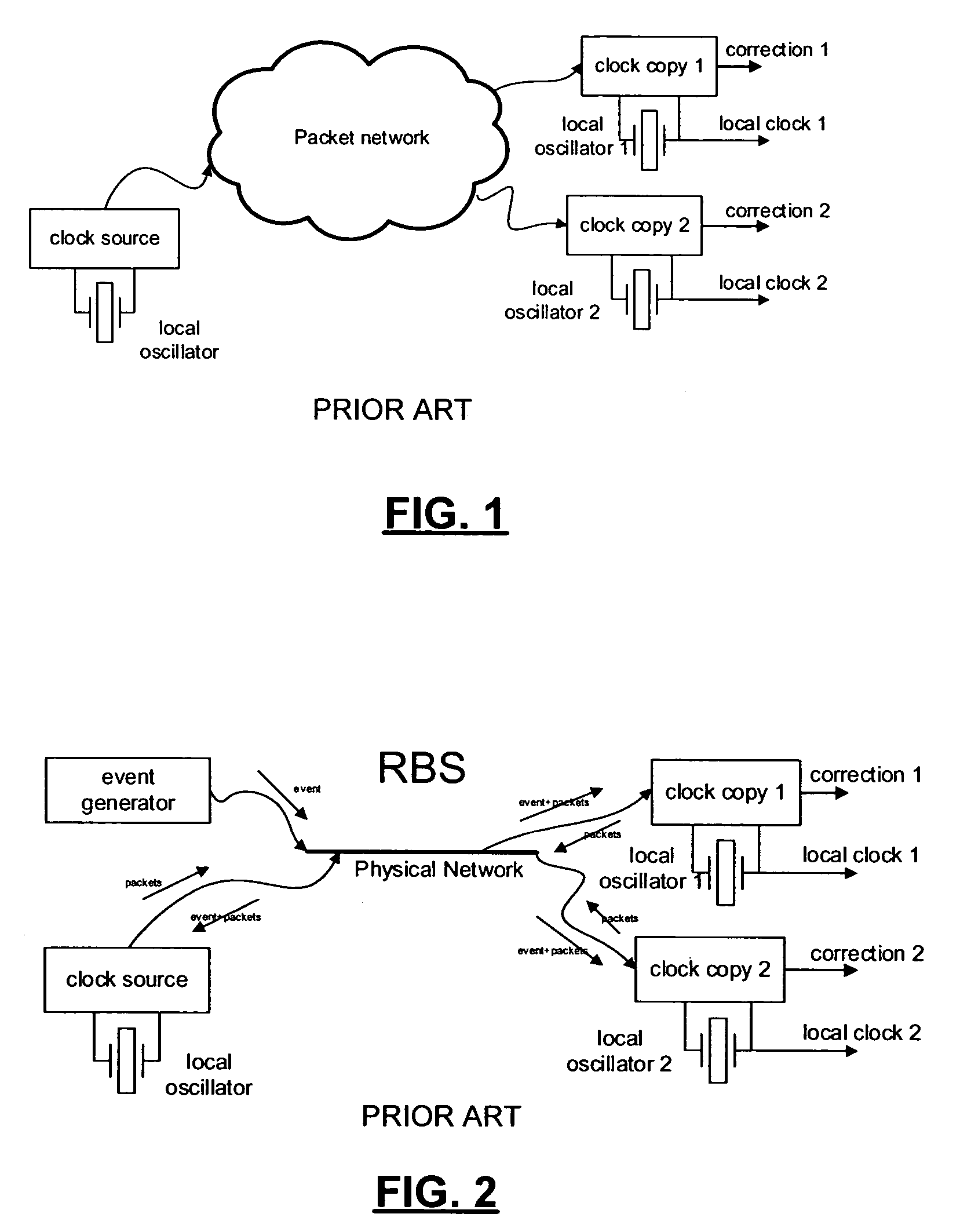
[0033]As discussed above, RBS normally requires a physical medium to be present directly between the nodes. It does not work well when switches and routers that do not support RBS are present since they introduce a large delay that RBS cannot handle.

[0034]In the discussion of RBS, the set of delay components falls into four parts:[0035]Send Time. This is the time necessary construct a message. In a hardware environment, it can be made very small fairly easily; in a computer environment higher priority interrupts will interfere.[0036]Access Time. This is the time required gain access to the physical medium. I can be quite large as a result of contention control, for example, in Ethernet.[0037]Propagation Time. This is typically very small, although in telecommunications the variation of propagation delay is a factor of importance (also due to the long lines).[0038]Receive Time. This is the time necessary on the receive side to properly detect the message. Like the Send Time, it is de...


PUM


Abstract

Disclosed is a method and apparatus for aligning clock domains over an asynchronous network between a source controlled by a first clock and a destination controlled by a second clock. The predicted delay is estimated for transmitting packets between a source and destination over the network. The time-stamped synchronization packets are sent to the destination, each time-stamped synchronization packet carries timing information based on a master clock at the source. A set of synchronization packets are received at the destination to create a set of data points, and the set of data points is weighted so that synchronization packets exhibiting a delay further from the expected delay are accorded less weight than synchronization packets exhibiting a delay closer to the expected delay. The expected delay is updated to create a current delay estimate based on the set of data points taking into account the different weighting of the data points. These steps are continually repeated on new sets of data points created from newly received synchronization packets using the current delay estimate for the expected delay. And a clock domain at the destination is continually aligned with a clock domain at the source based on the current delay estimate for packets traversing the network between the source and destination.

Description

CROSS-REFERENCE TO RELATED APPLICATION[0001]This application claims the benefit under 35 USC 119(e) of U.S. Provisional Application No. 60 / 448,739 filed Feb. 20, 2003, the contents of which are incorporated by reference herein.FIELD OF THE INVENTION[0002]The present invention relates to the field of digital communications. More specifically, the present invention relates to a method of aligning clock domains in packet networks.BACKGROUND OF THE INVENTION[0003]When isochronous services, such as voice or video, are transported over a packet network, some means must be provided for carrying timing information over the network. Several well known methods exist for transmitting a clock over a packet network. Methods that currently are in use include Plesiochronous mode, Synchronous Residual Time Stamp (SRTS) described in U.S. Pat. No. 5,260,978, Fleisher et al., or variant RTS method, Adaptive Clock Recovery (ACR), and combinations thereof. These methods rely either on the availability o...

Claims


Application Information

Patent Timeline
Patent Type & Authority Patents(United States)
IPC IPC(8): H04L12/28G06F1/12H04J3/06H04L7/00
CPCH04J3/0632H04J3/0664H04J3/06H04L2012/5603
Inventor REPKO, WILLEM L.VAN DER VALK, ROBERTUS L.SIMONS, PETRUS W.BARRACK, CRAIG
Owner ZARLINK SEMICON LTD
Why Eureka
Try Eureka