
Apparatus and method for inspecting defects

a technology of defect inspection and defect detection, applied in the direction of semiconductor/solid-state device testing/measurement, instruments, image data processing, etc., can solve the problems of short circuit, insulation failure, short circuit of wiring formed on it, etc., and achieve high efficiency, high reliability, and high reliability

Inactive Publication Date: 2008-01-01
HITACHI HIGH-TECH CORP
View PDF17 Cites 17 Cited by
  • Summary
  • Abstract
  • Description
  • Claims
  • Application Information

AI Technical Summary

Benefits of technology

[0010]In addition, another object of the present invention is to provide a method for producing a semiconductor substrate, by which a semiconductor substrate free from a defect can be produced with high reliability and high efficiency by enabling hundred percent inspection or random inspection with sufficient frequency so that a scratch, etc. showing shape variations, which are produced on the surface, are discriminated from an adhered particulate foreign material to inspect them when the polishing process or the grinding process, such as CMP, is performed for an object to be fabricated (for example, an insulating layer on a semiconductor substrate).
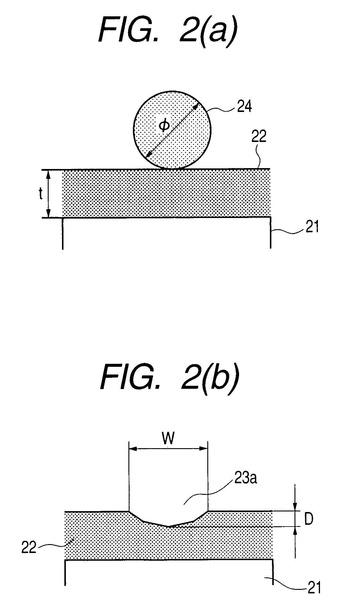
[0011]In addition, another object of the present invention is to provide a method for producing a semiconductor substrate, by which a semiconductor substrate free from a defect can be produced with high reliability and high efficiency by enabling discrimination of a concave defect such as a thin film-like foreign material and a scratch, which has a low height and a shallow depth, from a convex defect such as a particulate foreign material, which has a high height, to inspect the defects.

Problems solved by technology

In this manner, if a scratch showing shape variations is produced on the surface of the object to be fabricated in the semiconductor production and the magnetic head production, etching will become insufficient in wiring formed on the scratch, which causes a failure such as short circuit.
In addition to it, at the same time, if a foreign material adheres, a failure such as an insulation failure or a short circuit of wiring formed on it is caused.
Therefore, an operator conventionally performed visual inspection for review using an electron microscope to discriminate between a scratch showing shape variations and a foreign material, which required a long review time.
As a result, measures against a scratch or a particulate foreign material are delayed, which causes a large quantity of wafers to be polished continuously in bad conditions, resulting in a great loss in profit.

Method used


Image

  • Apparatus and method for inspecting defects
  • Apparatus and method for inspecting defects
  • Apparatus and method for inspecting defects

Examples


Embodiment Construction

[0079]Embodiments of a defect-inspecting apparatus and method according to the present invention, which are used in a semiconductor production process or a magnetic head production process, and which aim to operate a planarization fabrication process with stability, will be described with reference to drawings as below.

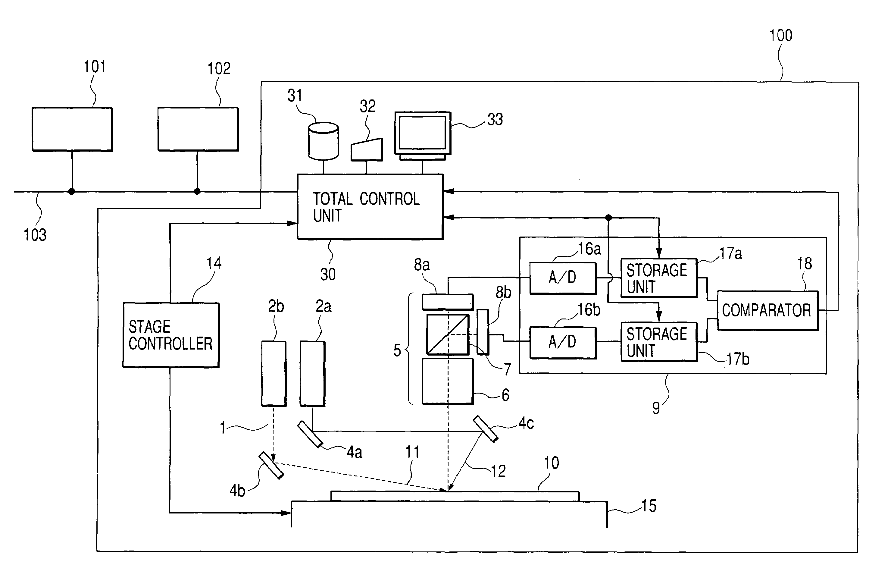
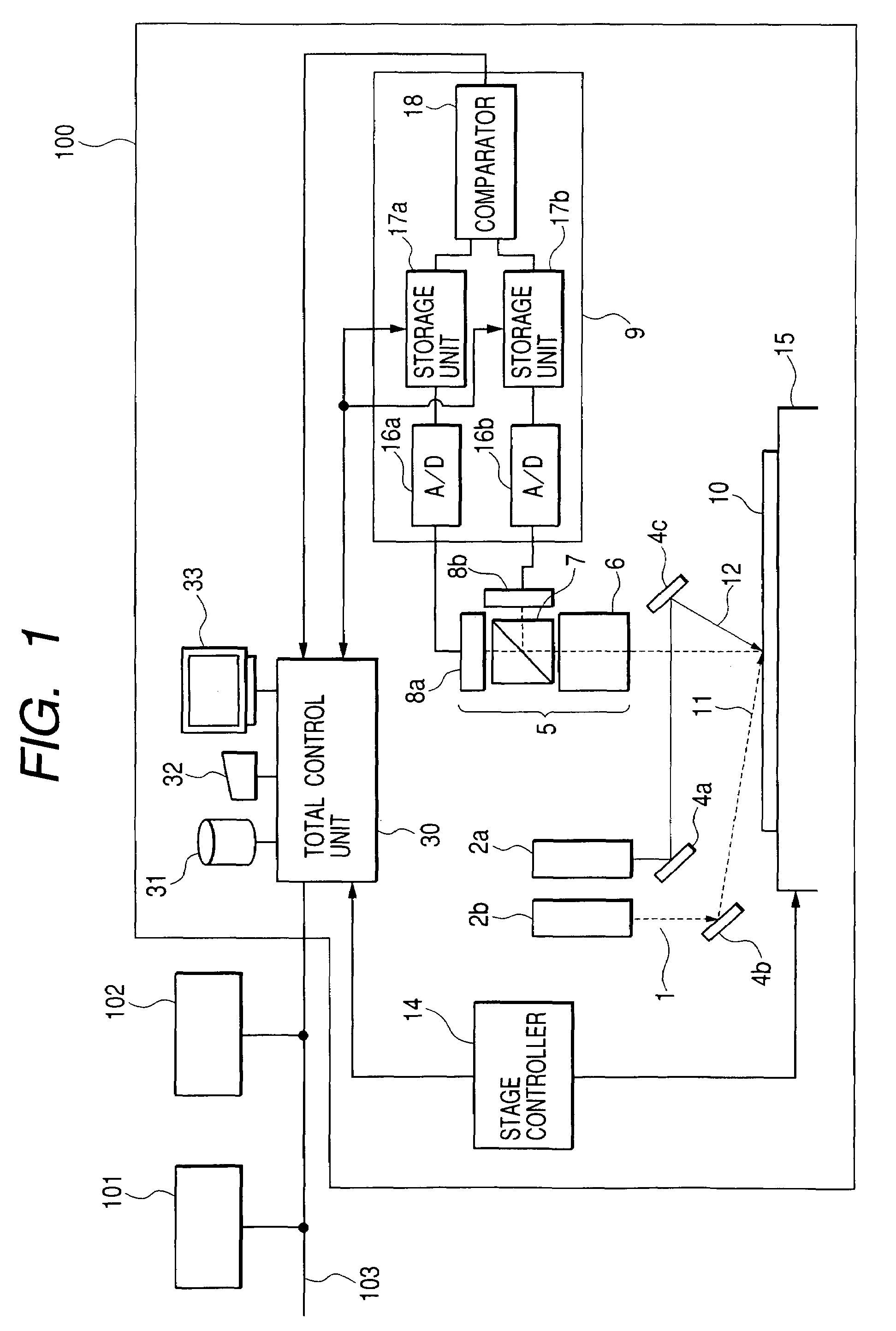
[0080]In the first place, a first embodiment of the defect-inspecting apparatus and its method according to the present invention will be described. As shown in FIG. 1, the present invention relates to a defect-inspecting apparatus 100 that performs sampling inspection or hundred-percent inspection of products in the middle of a semiconductor production process. As regards a semiconductor production line, a process-control computer 101 manages production conditions, for example, through a network 103, or for each individual production equipment (not illustrated). In the middle of the process, a semiconductor is inspected using a foreign-material inspecting apparatus, ...


PUM

PropertyMeasurementUnit
elevation angleaaaaaaaaaa
sizeaaaaaaaaaa
width Waaaaaaaaaa

Abstract

A defect-inspecting apparatus including an arrangement to convert detected light into a first signal corresponding to light illuminated by a high-angle illumination optical system and / or a second signal corresponding to light illuminated by a low-angle illumination optical system; and a classification unit which utilizes the first and second signal and classifies defects on the object to be inspected, wherein a defect size is estimated by changing a correction coefficient of the defect size on a basis of a concave-convex level (b / a), where the concavo-convex level (b / a) of a defect is indicated by a ratio of a size b of a first direction of the defect to a size a of a second direction of the defect, where the second direction is lateral to the first direction.

Description

CROSS REFERENCE TO RELATED APPLICATION[0001]This is a continuation of U.S. application Ser. No. 10 / 050,776, filed Jan. 18, 2002 now U.S. Pat. No. 7,187,438. This application relates to and claims priority from Japanese Patent Application No. 2001-056547, filed on Mar. 1, 2001. The entirely of the contents and subject matter of all of the above is incorporated herein by reference.BACKGROUND OF THE INVENTION[0002]The present invention relates to a defect-inspecting apparatus and a defect-inspecting method, which are used for inspecting defects such as a scratch or a particulate foreign material by discrimination; the defects occur in a planarization fabrication process based on polishing or grinding fabrication technique, which is used in semiconductor production and in magnetic head production.[0003]As a prior art that inspects a foreign material, which adheres to a semiconductor wafer where a circuit pattern is formed, by discriminating the foreign material from a circuit pattern, J...

Claims


Application Information

Patent Timeline
Patent Type & Authority Patents(United States)
IPC IPC(8): G01N21/00G01B11/30G01N21/88G01N21/956G06T1/00G06T7/60H01L21/66
CPCG01N21/9501
Inventor HAMAMATSU, AKIRANOGUCHI, MINORIOOSHIMA, YOSHIMASANISHIYAMA, HIDETOSHIWATANABE, TETSUYA
Owner HITACHI HIGH-TECH CORP
Learn More