
Transmission device for transmitting electrical signals between a rotor and a stator

a transmission device and stator technology, applied in the direction of electrically conductive connections, rotary current collectors, electrolytic capacitors, etc., can solve the problems of unnecessary wear and tear of moving intermediate elements, noise generation or noise generation

Active Publication Date: 2007-12-25
VALEO SCHALTER & SENSOREN
View PDF5 Cites 5 Cited by
  • Summary
  • Abstract
  • Description
  • Claims
  • Application Information

AI Technical Summary

Benefits of technology

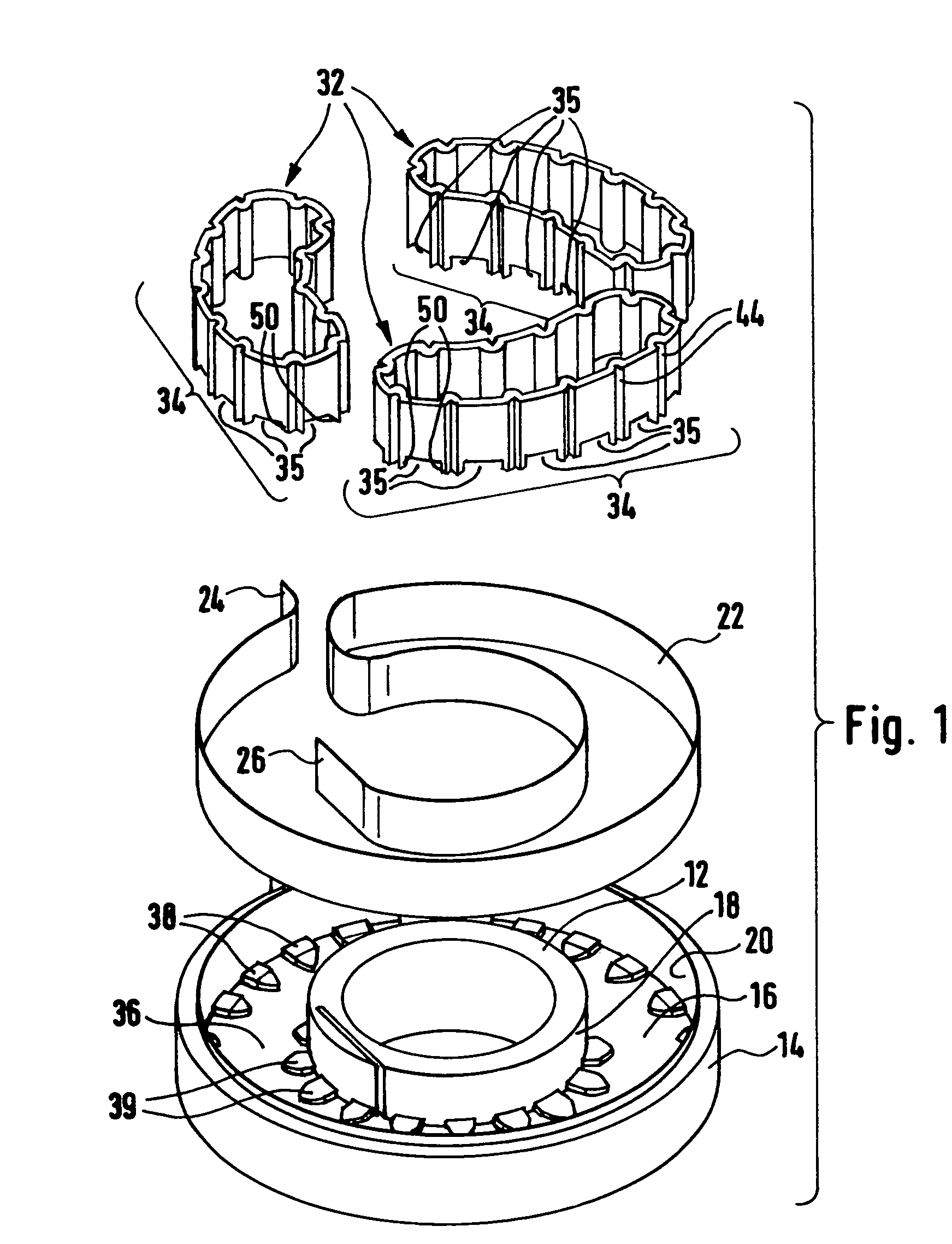
[0007]This object is achieved with a transmission device of the above-mentioned type in that the annular band can be driven by the rotor and / or by the stator via engagement sections provided on the annular band side. The rotor and / or the stator thereby preferably directly drive the annular band, i.e. without further connecting intermediate movable parts, which leads to secure rolling of the annular band in the space. Undesired motion or slipping and possible consequent impairment of the rotary motion of the rotor is prevented by the annular band drive. Movable intermediate elements which generate undesired noise or cause undesired wear are unnecessary.
[0008]The elastic properties of the annular band allow the annular band to completely fill the space in a radial direction and to suitably load the flat strip cable against both the rotor and stator. If the flat strip cable is wound several times on the rotor and / or stator, the annular band can compensate for the varying width of the space. Due to its pretension, the annular band flatly abuts the rotor and the stator. Rattling noises caused by the annular band in the space are eliminated. The annular band may be largely circular in the disassembled state.
[0010]In a preferred embodiment of the invention, the engagement sections are formed on the upper and / or lower edge of the annular band in the form of tooth-gap-like recesses which cooperate with complementary tooth-like drive sections of the rotor and / or of the stator to drive the annular band. The engagement sections on the upper and / or lower edge of the annular band facilitate an effective drive of the annular band without influencing the flat strip cable or impairing its motion. The engagement sections and the tooth-gap-like recesses thereby project past the flat strip cable. The tooth-like drive sections of the rotor or of the stator are correspondingly disposed above or below the free longitudinal edge of the flat strip cable.
[0011]The drive sections of the rotor and / or of the stator are preferably disposed on the bottom of the space. The drive sections can cooperate with the engagement sections of the annular band without impairing the flat strip cable.
[0012]In accordance with the invention, the drive sections may extend in an axial and radial direction such that the free edge of the flat strip cable may be supported on the drive sections. The drive sections on the rotor and / or on the stator consequently serve not only to drive the annular band but also as supports for the respectively free edge of the flat strip cable. The overall friction on the free longitudinal edges of the flat strip cable is thereby reduced since the flat strip cable is only partially supported.
[0013]In a further embodiment of the invention, the drive sections have a cuboid main part and an end part which tapers down towards the bottom in a radial direction facing the space. In particular, the tapering end part ensures safe guidance of the flat strip cable in a radial direction such that the flat strip cable is safely supported on the cuboid main part thereby preventing blockage or jamming of the flat strip cable on the drive sections.

Problems solved by technology

Movable intermediate elements which generate undesired noise or cause undesired wear are unnecessary.

Method used


Image

  • Transmission device for transmitting electrical signals between a rotor and a stator
  • Transmission device for transmitting electrical signals between a rotor and a stator
  • Transmission device for transmitting electrical signals between a rotor and a stator

Examples


Embodiment Construction

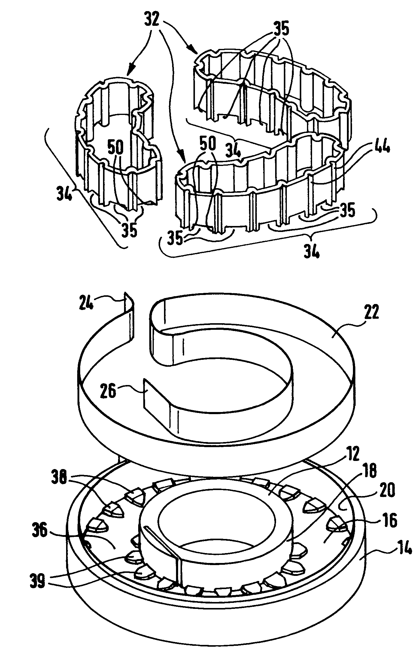
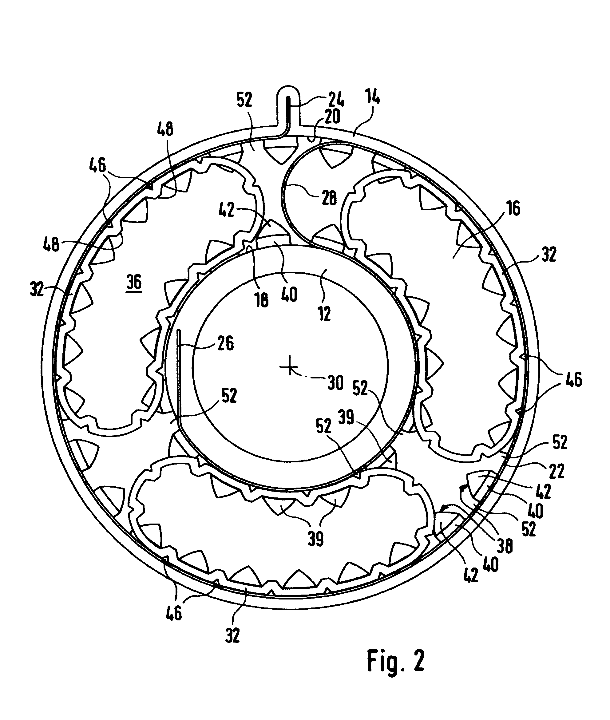
[0021]FIGS. 1 and 2 show an inventive transmission device 10. The transmission device 10 transmits electrical signals between a rotor 12 and a stator 14. The rotor 12 can thereby be coupled to a steering wheel or a steering shaft of a vehicle. The stator may be disposed on the chassis side and therefore does not follow the rotary motion of the rotor 12. An annular space 16 is provided between the rotor 12 and the stator 14 which is radially delimited by the outer wall 18 of the rotor 12 and the inner wall 20 of the stator 14. The space 16 of the transmission device 10 of FIGS. 1 and 2 is open at the top. The open side of the space 16 can be covered by a cover element (not shown).

[0022]A flat strip cable 22 for transmitting electrical signals is disposed between the rotatable rotor 12 and the non-rotatable stator 14. One free end 24 of the flat strip cable 22 is disposed on the stator side and the other free end 26 is disposed on the rotor side.

[0023]FIG. 2 shows that the flat strip ...


PUM

PropertyMeasurementUnit
Deformation enthalpyaaaaaaaaaa

Abstract

The invention concerns a transmission device for transmitting electrical signals between a rotor and a stator, having an annular space formed by the rotor and the stator, wherein the space receives at least one flat strip cable which extends between the rotor and the stator and can be wound and unwound in the space, and wherein at least one elastically resilient annular band is provided to support the flat strip cable in the space. The invention is characterized in that the annular band can be driven by the rotor and / or the stator via engagement sections provided on the side of the annular band.

Description

[0001]This application is the national stage of PCT / EP2004 / 007007 filed on Jun. 29, 2004.BACKGROUND OF THE INVENTION[0002]The invention concerns a transmission device for transmitting electrical signals between a rotor and a stator, having an annular space formed by the rotor and stator, wherein the space receives at least one flat strip cable which extends between the rotor and the stator and which can be wound and unwound in the space, wherein at least one elastically resilient annular band is provided in the space to support the flat strip cable.[0003]A transmission device of this type may be used e.g. in the steering column region of a vehicle, wherein the rotor is disposed on the steering wheel side and the stator is disposed on the chassis side. In modern vehicles, a plurality of functions are actuated via steering wheel switches. The inventive transmission device can transmit the electrical signals triggered by the switches to users or control devices on the chassis side, whi...

Claims


Application Information

Patent Timeline
IPC IPC(8): H01R39/00B60R16/027H01G9/00H01G9/012H01G9/08
CPCB60R16/027Y10T29/41Y10T29/417
Inventor SIMONIS, KARLLIPFERT, RAINERHASCH, MARTINGRUENER, ROLANDBINDER, BERNDSUCHANEK, JURGEN
Owner VALEO SCHALTER & SENSOREN
Learn More