
Cleaning mechanism having water spray function and photovoltaic panel cleaning equipment having same

a technology of cleaning mechanism and photovoltaic panel, which is applied in the direction of cleaning using liquids, solar heat collector safety, gearing, etc., can solve the problem of sharp increase in the number of photovoltaic panels to be cleaned, and achieve the effect of improving the overall cleaning effect or performance, preventing the cleaning member from idling, and preventing the cleaning member from being twisted

Active Publication Date: 2017-11-16
BOSON ROBOTICS LTD
View PDF0 Cites 5 Cited by
  • Summary
  • Abstract
  • Description
  • Claims
  • Application Information

AI Technical Summary

Benefits of technology

The present invention provides a cleaning mechanism for photovoltaic panels that uses water spray to improve cleaning performance. The cleaning member is connected to a self-locking device that can stop the cleaning member from idling and reduce wear and tear on the panel. The cleaning mechanism can also include an obstacle crossing mechanism and a telescopic mechanism to easily move the cleaning equipment from one photovoltaic panel array to another. The use of the cleaning mechanism and the photovoltaic panel cleaning equipment of the present invention can make the adhesive materials on the photovoltaic panels wet and conveniently swept away by the cleaning member and sweeping member, leading to improved power generation efficiency.

Problems solved by technology

With the construction of more and more solar photovoltaic power plants, the number of photovoltaic panels which need to be cleaned increases sharply, and how to rapidly clean the photovoltaic panels and simultaneously guarantee the cleaning effect has already been a problem which needs to be urgently solved by photovoltaic power generation enterprises.

Method used


Image

  • Cleaning mechanism having water spray function and photovoltaic panel cleaning equipment having same
  • Cleaning mechanism having water spray function and photovoltaic panel cleaning equipment having same
  • Cleaning mechanism having water spray function and photovoltaic panel cleaning equipment having same

Examples


Embodiment Construction

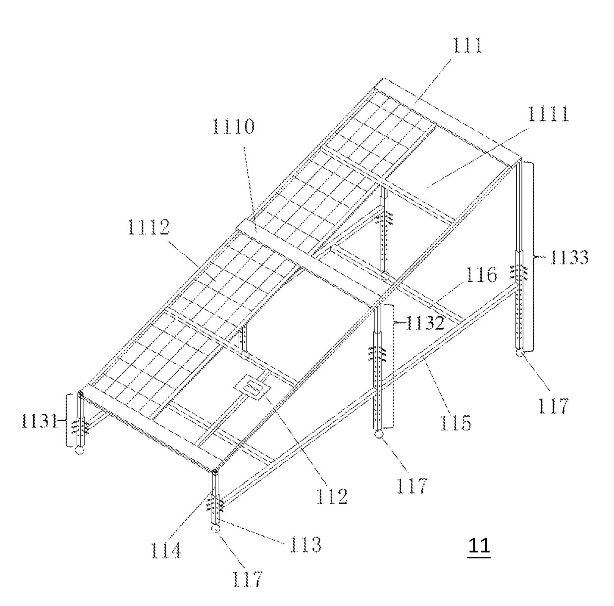
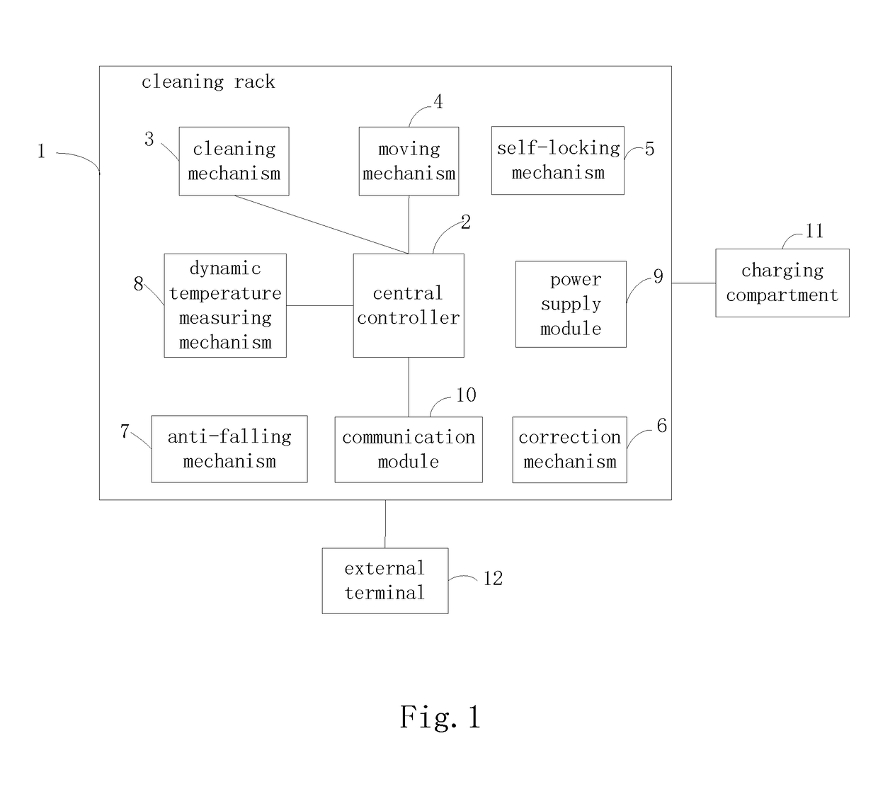
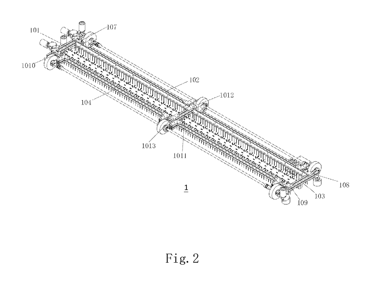
[0032]The above-mentioned and other technical features and advantages of the present invention will be further described below in detail with reference to the drawings. Preferred Embodiment 1: As illustrated in FIG. 1 which illustrates a functional diagram of a photovoltaic panel cleaning equipment disclosed in accordance with an embodiment of the present invention, the photovoltaic panel cleaning equipment comprises a body, a charging compartment 11 and an external terminal 12. The body of the photovoltaic panel cleaning equipment comprises a cleaning rack 1, a central controller 2, a cleaning mechanism 3, a moving mechanism 4, a self-locking mechanism 5, a correction mechanism 6, an anti-falling mechanism 7, a dynamic temperature measuring mechanism 8, a power supply module 9 and a communication module 10, wherein the central controller 2, the cleaning mechanism 3, the moving mechanism 4, the self-locking mechanism 5, the correction mechanism 6, the anti-falling mechanism7, the dy...


PUM


Abstract

A cleaning mechanism having a water spray function adapted for cleaning photovoltaic panel is provided, which includes a cleaning rack, a cleaning member and a sweeping member. Cleaning rack includes several connecting rods detachably connected; Cleaning member is detachably mounted between the connecting rods and used for stripping off adhesive materials on photovoltaic panel; the sweeping member being detachably mounted on connecting rods and used for sweeping the adhesive materials away from the photovoltaic panel. A water spray device is detachably mounted on the cleaning rack used for wetting adhesive materials. The water spray device includes a water spray pipe and a water storage tank, and a spray nozzle atomizing water. A cleaning member power unit is detachably connected with the cleaning member and is used for driving the cleaning member to rotate; and the cleaning member power unit comprises a self-locking device used for preventing cleaning member from idling.

Description

FIELD OF THE INVENTION[0001]The present invention relates to the technical field of solar power generation, and in particular to a cleaning mechanism have water spray function, adapted for use on a photovoltaic panel, and to a photovoltaic panel cleaning equipment having the same.BACKGROUND OF THE INVENTION[0002]With the comprehensive development of global industrialization, demands of all industries in all countries for energy increase sharply, and the amount of energy demands has already been a standard for measuring the situation of economic development of a country or a region. Renewable energy mainly includes hydraulic energy, solar energy, wind energy, geothermal energy, biomass energy, etc., and the most important feature thereof is that it has a self-restoring capacity, renewable energy can be continuously replenished from the nature in a use process by people, and it is energy which is inexhaustible and will never be used up. As studied and proved by scholars, people common...

Claims


Application Information

Patent Timeline
Patent Type & Authority Applications(United States)
IPC IPC(8): H02S40/10B08B3/02B08B1/00B08B7/04B08B1/04
CPCH02S40/10B08B3/024B08B1/04B08B1/002B08B7/04B08B2203/0223B08B2220/01B08B3/04B08B13/00B08B11/04B08B3/02F16H1/16H02K7/1166B08B1/30B08B1/12B08B1/32A46B2200/30F24S40/20Y02E10/50Y02E10/40B08B1/20B08B1/34
Inventor WANG, GUANYUZHANG, JINGGONGQIAN, ZHIHONG
Owner BOSON ROBOTICS LTD
Learn More