
Utility vehicle with air-intake apparatus for engine

Active Publication Date: 2012-06-21
KAWASAKI MOTORS LTD
View PDF7 Cites 28 Cited by
  • Summary
  • Abstract
  • Description
  • Claims
  • Application Information

AI Technical Summary

Benefits of technology

[0008]The present invention is achieved in consideration with the above problem, and an object of the present invention is to effectively utilize a space in a bonnet chamber by utilizing an upper space of an air cleaner case arranged in the bonnet chamber for arranging vehicle equipments. One of other objects is to easily perform maintenance of the interior of the air cleaner case. Further, another one of other objects of the present invention is to prevent water and mud from entering the air cleaner case from the exterior.

Problems solved by technology

Therefore, various components for the vehicle cannot be arranged in an upper space of the air cleaner case 121 and in the vicinity thereof, and a space in the bonnet chamber cannot be effectively utilized.
Thus, a maintenance task takes time and effort.

Method used


Image

  • Utility vehicle with air-intake apparatus for engine
  • Utility vehicle with air-intake apparatus for engine
  • Utility vehicle with air-intake apparatus for engine

Examples


embodiment 1

Effects of Embodiment 1

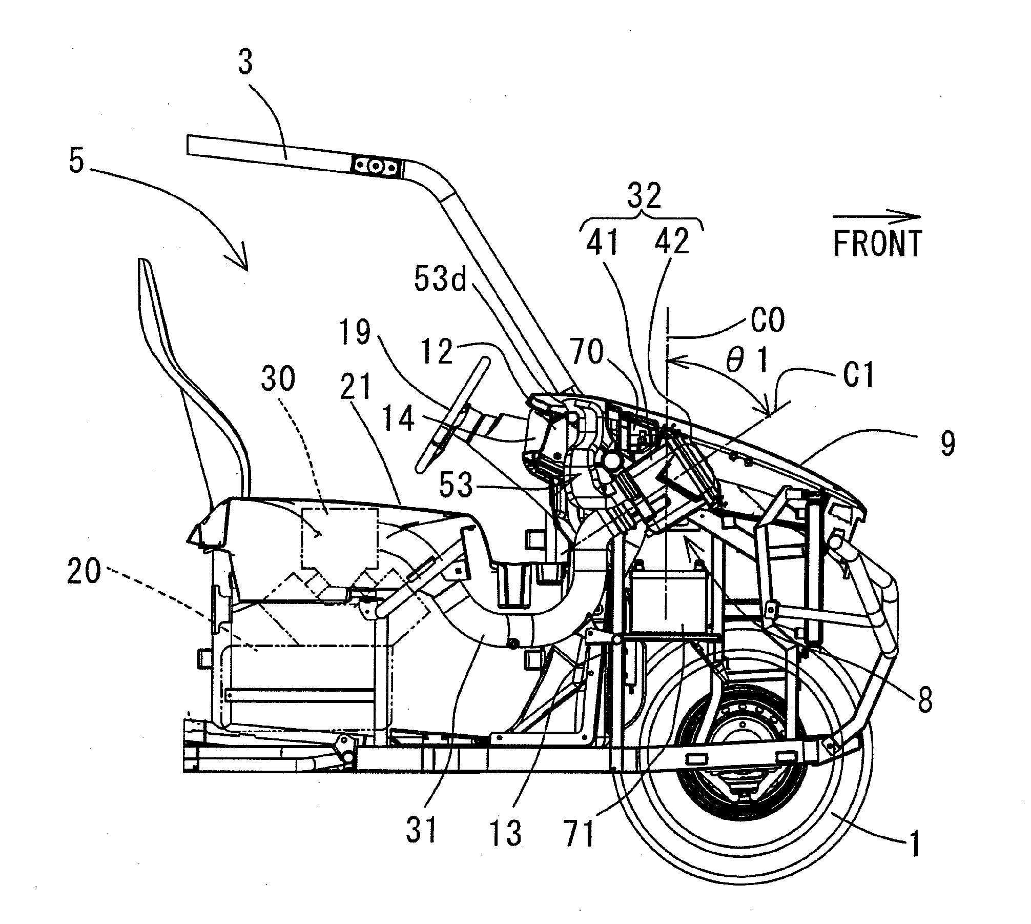
[0058](1) As shown in FIGS. 3 and 4, the air cleaner case 32 is arranged to be inclined so that the central axis C1 of the filter element 44 is inclined forward. Thus, a space in an upper rear part of the air cleaner case 32 can be effectively utilized for arranging the components 70 for vehicle without disturbing maintenance of the air cleaner case 32, so that the air cleaner case 32 can be compactly arranged in the bonnet chamber 8.

[0059](2) In the case main body 41, the central axis C1 of the filter element 44 is inclined forward relative to the vertical line C0. Thus, upon attachment and detachment tasks of the filter element 44, even a short person can view the interior of the air cleaner case 32 so as to easily attach and detach the filter element 44.

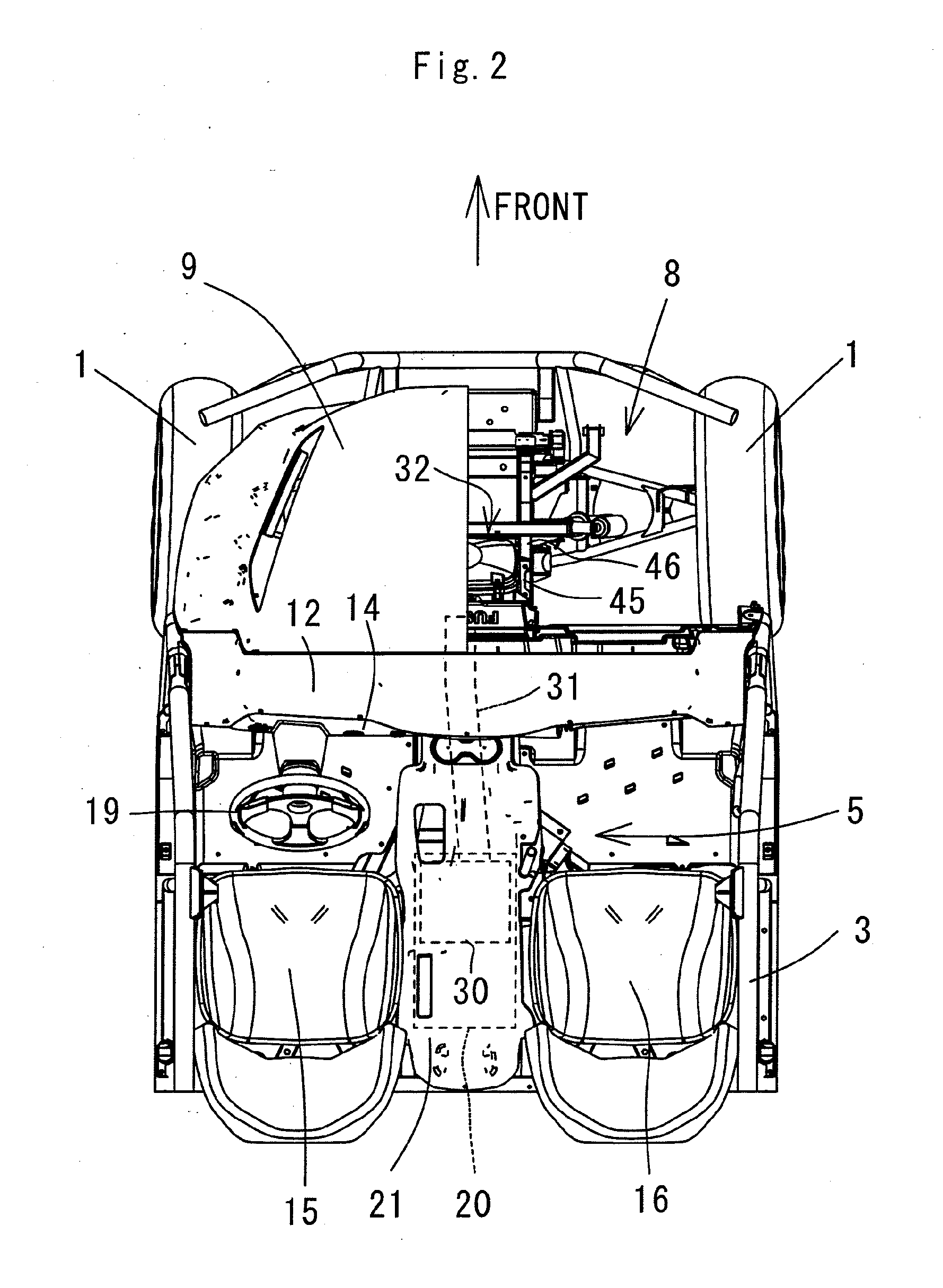
[0060](3) As shown in FIGS. 1 to 3, the snorkel 53 is arranged in the dashboard 12, and the combustion air is taken in from the interior of the dashboard 12. Thus, fresh air can always be taken in, and mud, ...


PUM


Abstract

The present invention relates to a utility vehicle with an air-intake apparatus for an engine. The air-intake apparatus includes an air-intake duct connected to the engine, the air-intake duct extending in a bonnet chamber, and an air cleaner case connected to an air-intake upstream portion of the air-intake duct, the air cleaner case accommodating a tubular filter element, the air cleaner case being arranged to be inclined in the bonnet chamber so that a central axis of the filter element is inclined forward.

Description

BACKGROUND OF THE INVENTION[0001]1. Field of the Invention[0002]The present invention relates to a utility vehicle with an air-intake apparatus for an engine for supplying combustion air to the engine, mainly to a utility vehicle suitable for running on irregular terrain.[0003]2. Description of the Related Art[0004]FIG. 10 shows one example of a conventional utility vehicle. A vehicle is provided with a cabin 110 surrounded by a cabin frame (ROPS) 111 between a pair of right and left front wheels 101 and a pair of right and left rear wheels 102. A seat 104 is installed in the cabin 110, and an engine 105 is arranged on the lower side of the seat 104. A bonnet 112 is provided on the front side of the cabin 110, and the bonnet 112 covers the upper side of a bonnet chamber 113.[0005]An air-intake apparatus for supplying combustion air to the engine 105 includes an air-intake chamber 115 arranged on the upper side of the engine 105, an air-intake duct 120 connected to the air-intake cha...

Claims


Application Information

Patent Timeline
IPC IPC(8): B60K13/02
CPCF02M35/162F02M35/04F02M35/024B60K13/02F02M35/048
Inventor AZUMA, SHINJIRO
Owner KAWASAKI MOTORS LTD
Learn More