
Air shroud for dissipating heat from an electronic component

a technology for electronic components and air shrouds, which is applied in the direction of electrical apparatus casings/cabinets/drawers, instruments, and semiconductor/solid-state device details. it can solve the problems of air guiding bodies not being able to effectively cover and seal electronic components, air guiding bodies not being able to effectively install and position air guiding bodies on circuit boards, etc., to achieve the effect of dissipating heat and dissipating heat from electronic components

Active Publication Date: 2007-12-18
SUPER MICRO COMP
View PDF7 Cites 64 Cited by
  • Summary
  • Abstract
  • Description
  • Claims
  • Application Information

AI Technical Summary

Benefits of technology

The air shroud effectively reduces the working temperature of electronic components by accelerating air flow through the passage and peripheral surfaces, accommodating components of different specifications and improving their lifespan.

Problems solved by technology

However, this device can only enable the air to flow in and out in the passage inside the air shroud, and is not provided with an object of dissipating heat from an electronic component with the air.
However, as height of internal space of the air guiding body is a constant, if an electronic component on a circuit board is taller, the air guiding body will not be able to effectively cover and seal the electronic component in an air passage of the air guiding body.
Furthermore, as a position and size of a notch installed by baffles at two sides of the air guiding body are constant, if the electronic component welded on the circuit board is larger in volume or taller in height, or the welding position is not corresponding to that of the notch, then the air guiding body will not be effectively installed and positioned on the circuit board.
The Taiwan Utility Patent M265675, “Computer Host and its Heat Dissipating Module,” discloses a flow guiding casing whose interior space is a constant; therefore, it can not be effectively adapted to a heat-generating electronic component of various volume or height.

Method used


Image

  • Air shroud for dissipating heat from an electronic component
  • Air shroud for dissipating heat from an electronic component
  • Air shroud for dissipating heat from an electronic component

Examples


Embodiment Construction

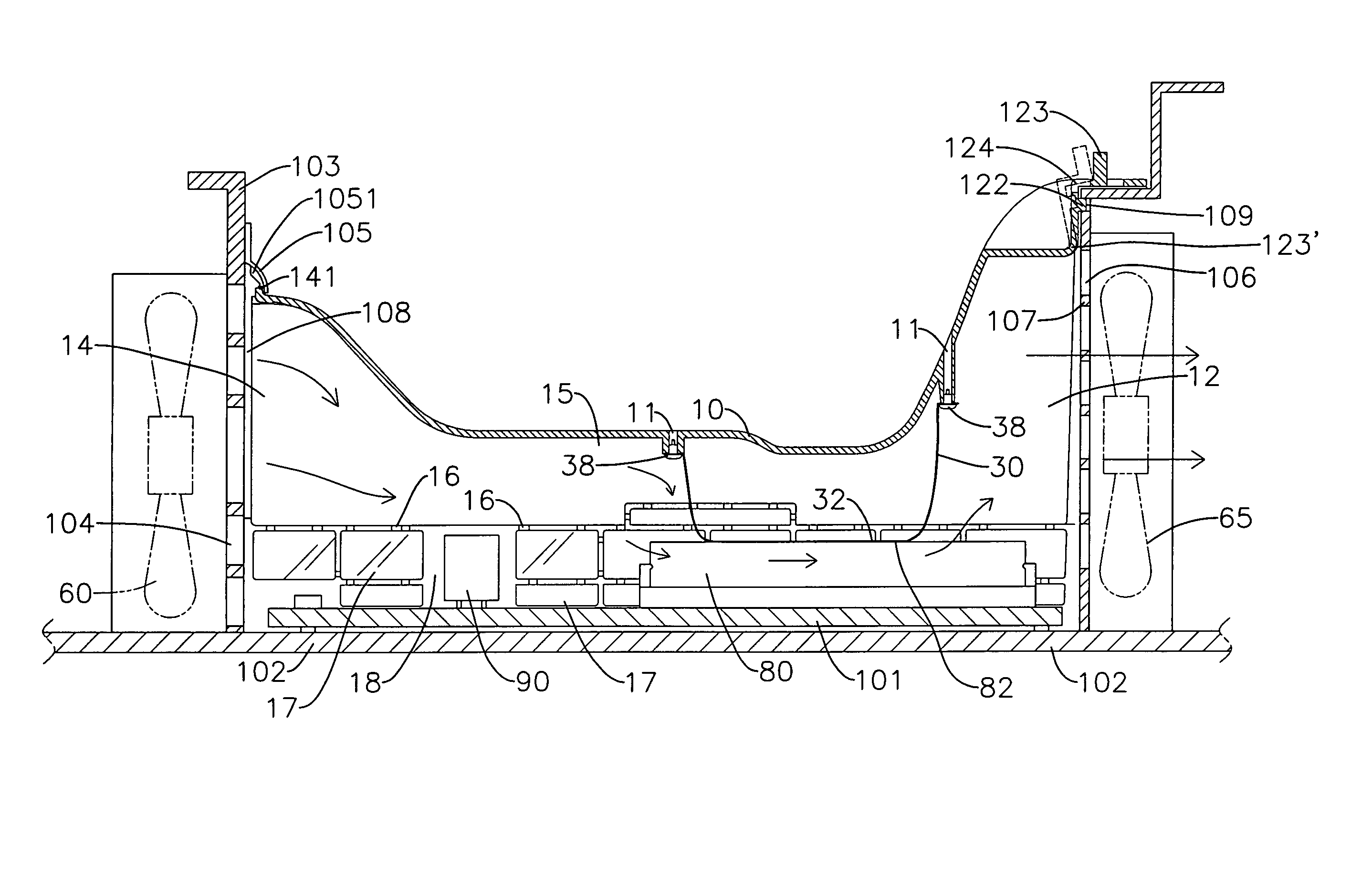
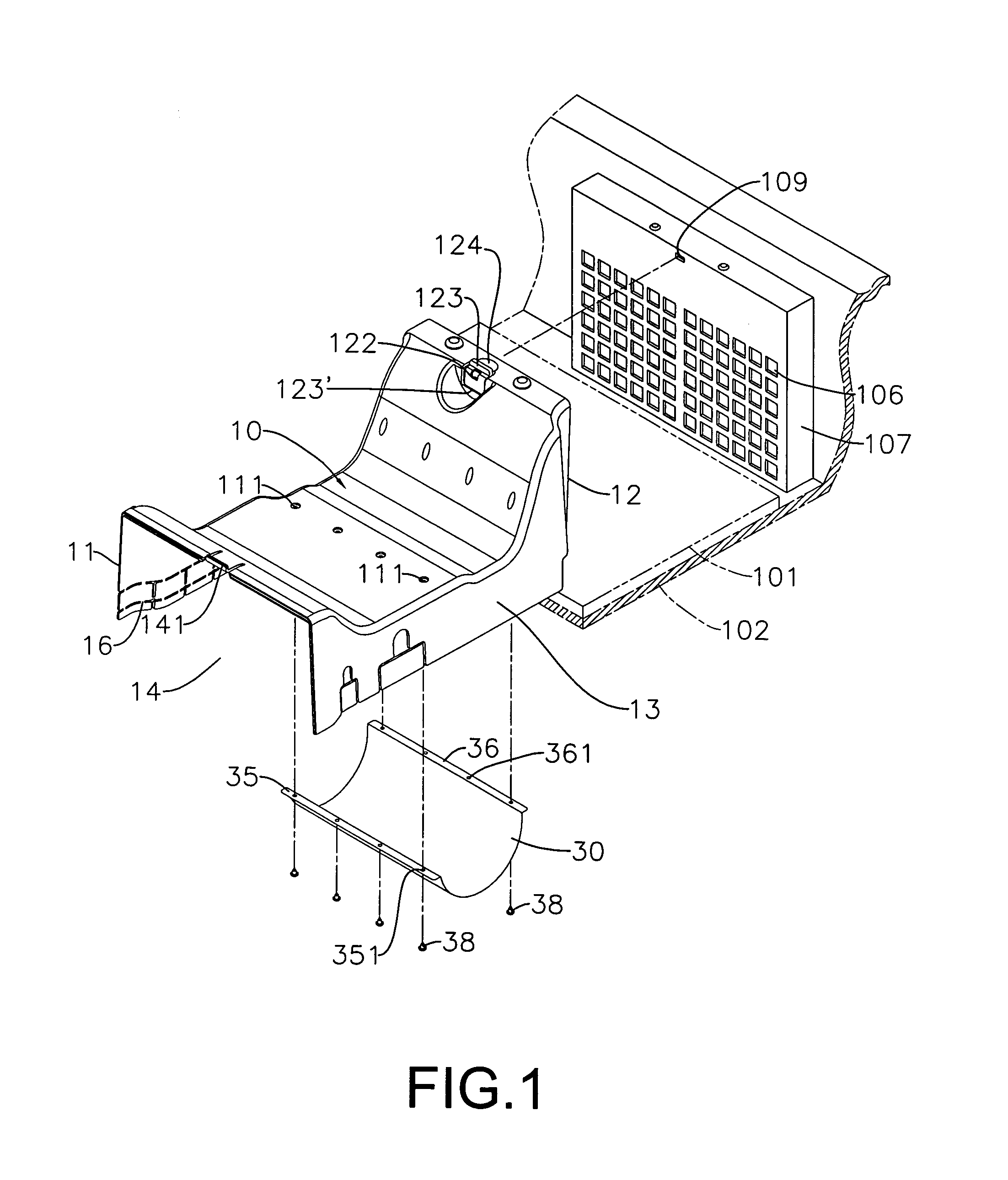
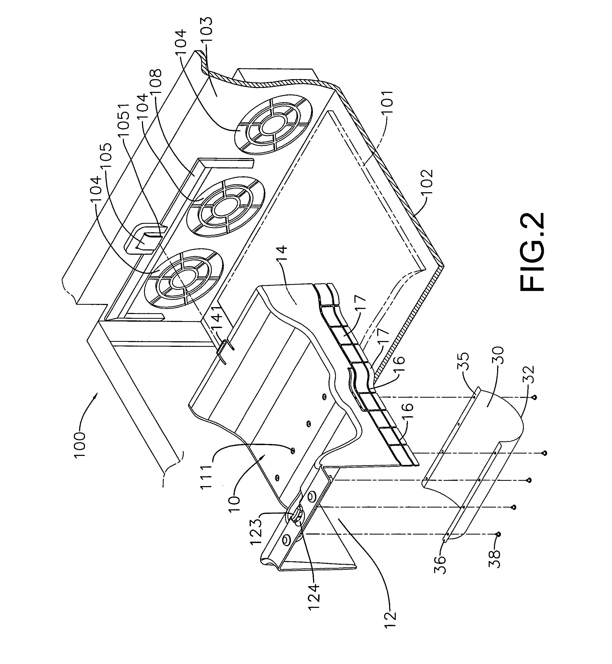
[0014]Referring to FIG. 1 and FIG. 2, the present invention is to provide a air shroud for dissipating heat from an electronic component, including a air shroud 10 of a pre-determined length and a roughly U-shaped cross section, which is provided with a first opening 12 and a second opening 14, wherein the first and second openings 12, 14 are interconnected to form a passage 15 for air flow. A modularized computer case 100 is provided with two vertical walls separated by a pre-determined distance, including a first wall 107 and a second wall 103, respectively. A circuit board 101 is installed on a base plate 102 of the computer case 100, and the air shroud 10 is covered on the circuit board 101, such that a specific electronic component 80 on the circuit board 101 can be located in the passage 15 (as shown in FIG. 3 and FIG. 4). The second opening 14 is corresponding to and connected on the second wall 103, whereas the first opening 12 is corresponding to and connected on the first ...


PUM


Abstract

A air shroud for dissipating heat from an electronic component is composed of a air shroud of a roughly U-shaped cross section, whose left and right sides are formed into a first and a second opening, respectively. A passage is formed between the first and second openings, enabling air to flow along a specific direction. A flexible thin piece is fixed inside the air shroud which covers a specific electronic component on a circuit board, and the flexible thin piece is touched with a surface of the electronic component. The fast-flowing air flows quickly along the passage, so as to effectively cool down a working temperature of the specific electronic component, thereby increasing a lifetime of usage of the specific electronic component.

Description

BACKGROUND OF THE INVENTION[0001]a) Field of the Invention[0002]The present invention relates to a air shroud for dissipating heat from an electronic component and more particularly to a air shroud installed in an interior of a computer case which can cover a specific electronic component on a circuit board. The air shroud is provided with an air entrance and an air exit, so as to form a passage for providing air to flow quickly, in an interior of the air shroud. A flexible thin piece is fixed in the passage, and the fast flowing air can be guided downward through the flexible thin piece, in order to enhance a heat dissipating by air to the specific electronic component.[0003]b) Description of the Prior Art[0004]The Taiwan Utility Patent M253826, Detachable “Air shroud without a Tool,” discloses a air shroud with two openings. A suction or ventilation fan is fixed on a top of an air passage of the air shroud, such that the air can be expelled out of the two openings in an opposite d...

Claims


Application Information

Patent Timeline
Patent Type & Authority Patents(United States)
IPC IPC(8): H05K7/20
CPCH05K7/20154
Inventor CHEN, RICHARD
Owner SUPER MICRO COMP
Learn More