
Arrangement for outboard motor

a technology for arranging outboard motors and motors, which is applied in the direction of steam power plants, special-purpose vessels, vessel construction, etc., can solve the problems of coupling mechanism contact, electrical components damaged, and extremely limited space within the cowling

Inactive Publication Date: 2002-02-12
SANSHIN KOGYO CO LTD
View PDF12 Cites 36 Cited by
  • Summary
  • Abstract
  • Description
  • Claims
  • Application Information

AI Technical Summary

Benefits of technology

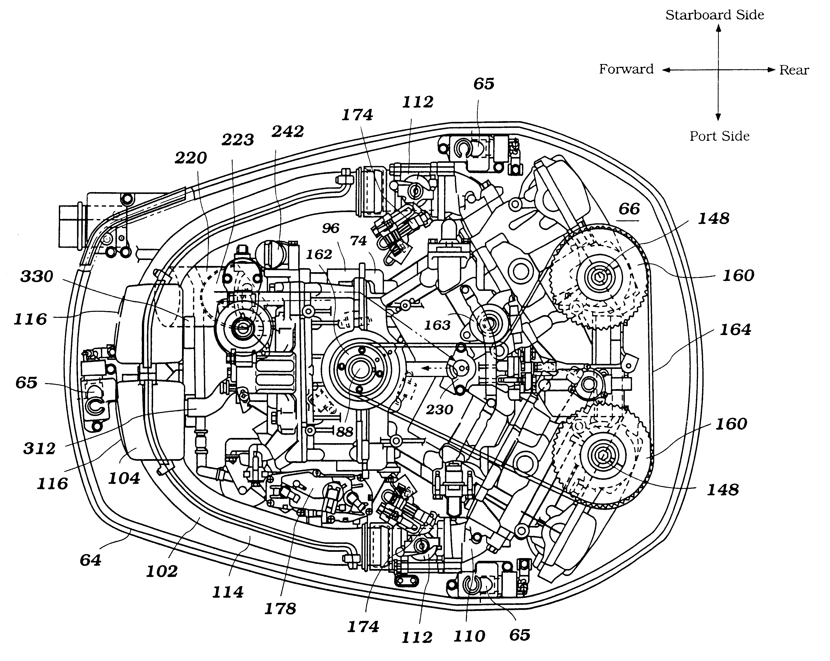
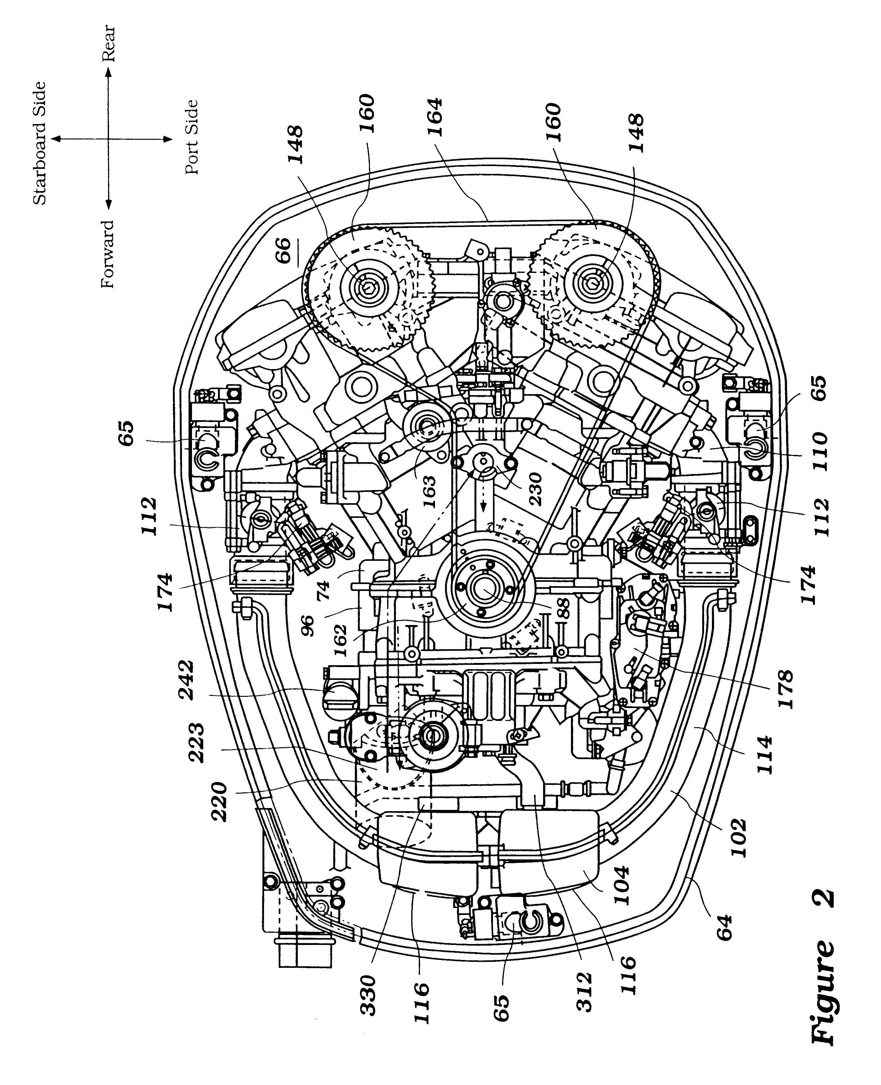
With particular reference to FIGS. 3 and 12, certain electrical components, the ECU 176, the starter motor 188, the rectifier regulator 190, the relay box 192, and the fuse box 194, preferably are disposed in a space S2 defined between the intake runners 114, the plenum chamber members 116, and the engine body 96. More preferably, these electrical components 176, 188, 190, 192, 194 are interposed between the crankcase cover 84b and the plenum chamber members 116. Most preferably, these electrical components are also located substantially beneath the flywheel cover 499 (see FIG. 9). It is also preferable that these electrical components 176, 188, 190, 192, 194 are supported by the crankcase cover 84b. For example, in the illustrated arrangement, the ECU 176, the starter motor 188 and the rectifier regulator 190 are positioned at an upper portion of the crankcase cover 84b. The ECU 176 and the rectifier regulator 190 are placed in parallel to the starter motor 188, and the regulator 190 is in a behind the ECU 176. The relay box 192 is positioned at a middle portion of the crankcase cover 84b and the fuse box 194 is positioned under the relay box 192. This arrangement is advantageous because it uses the space between the crankcase assembly 84 and the plenum chamber members 116, which reduces the size of the outboard motor 30. Moreover, in this arrangement, the plenum chamber members 116 and the intake runners 114 protect the electrical components 188, 190, 192, 194 from the coupling mechanism 65 when the top cowling member 62 is detached. Several features and advantages of the present invention can be achieved with less than all of these electrical components 176188, 190, 192, 194 positioned as described above. However, this arrangement described above is preferred because it efficiently protects these electrical components from damage caused by the coupling mechanism as described above.

Problems solved by technology

A general problem associated with outboard motors is that the space within the cowling is extremely limited.
In this limited space, many engine components must be disposed.
When the upper portion is removed from the lower portion, the coupling mechanism can contact and damage of these electrical components.

Method used


Image

  • Arrangement for outboard motor
  • Arrangement for outboard motor
  • Arrangement for outboard motor

Examples


Embodiment Construction

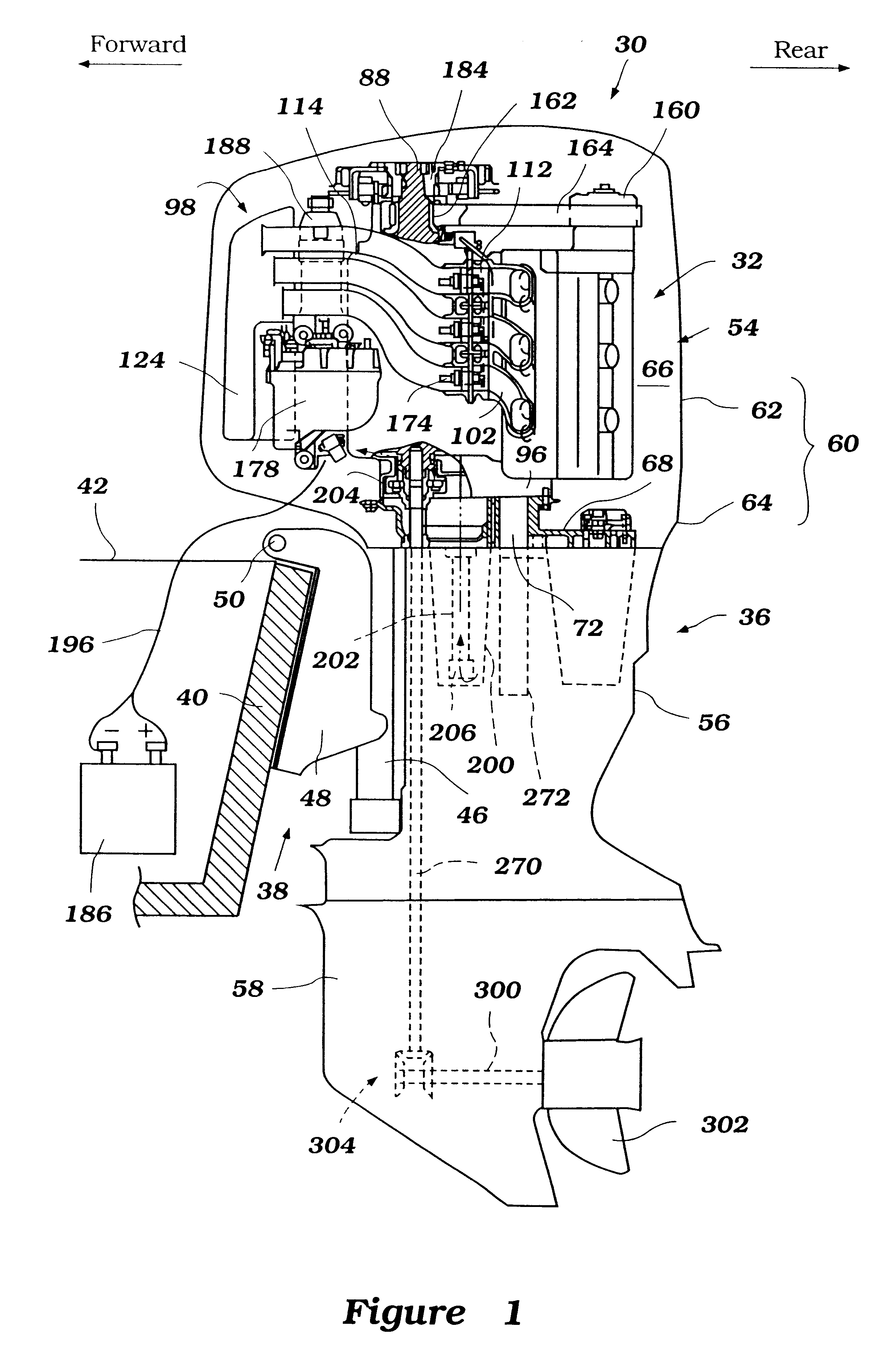
With primary reference to FIG. 1, an outboard motor 30 employs an internal combustion engine 32 configured in accordance with a preferred arrangement of the present invention. Although the present invention is shown in the context of an engine for an outboard motor, various aspects and features of the present invention also can be applied to engines for other types of marine outboard drive units (e.g., a stem drive unit) and also to other engines (e.g., land vehicle engines and stationary engines).

In the illustrated arrangement, the outboard motor 30 comprises a drive unit 36 and a bracket assembly 38. The bracket assembly 38 supports the drive unit 36 on a transom 40 of an associated watercraft 42 so as to place a marine propulsion device in a submerged position with the watercraft 42 resting on the surface of a body of water. The bracket assembly 38 comprises a swivel bracket 46, a clamping bracket 48, a steering shaft (not shown) and a pivot pin 50.

The steering shaft extends thro...


PUM


Abstract

An outboard motor comprises an internal combustion engine and a protective cowling that surrounds the engine. The cowling comprises at least an upper portion and a lower portion. The engine comprises a cylinder block that defines a cylinder bore. A cylinder head member is fixed at one end of the cylinder block and encloses one end of the cylinder bore. A crankcase member is fixed at the other end of the cylinder block and encloses the other end of the cylinder bore. The crankcase member forms a crankcase chamber. A piston is positioned within the cylinder bore. A crankshaft is rotably journaled in the crankcase chamber and is connected to the piston. The piston, the cylinder bore and the cylinder head together define a combustion chamber. The cylinder block, the cylinder head member and the crankcase member together defining an engine body. A first air intake conduit communicates with the engine and extends generally along a side of the engine body. The first air intake conduit communicates with an intake silencer located proximate the crankcase member. The engine further comprises a starter motor, an electronic control unit and a fuel supply system. The fuel supply system comprises a vapor separator and a fuel injector. The starter motor, the electronic control unit, the vapor separator and the fuel injectors are located in a space defined between the intake silencer, the first air intake conduit and the engine body.

Description

1. Field of the InventionThis invention relates to an improved arrangement of an outboard motor, and more particularly to an arrangement of an outboard motor that protects certain engine components.2. Description of Related ArtOutboard motors are powered by an internal combustion engine. The engine is surrounded by a protective cowling. The protective cowling typically comprises an upper portion and lower portion, which are removably mounted to each other by coupling mechanisms, such as, for example, hooks. Accordingly, the upper portion can be removed from the lower portion such that the engine can be inspected and / or repaired.A general problem associated with outboard motors is that the space within the cowling is extremely limited. In this limited space, many engine components must be disposed. For example, the engine includes many electrical components, which must be positioned in the limited space between the cowling and the engine. When the upper portion is removed from the lo...

Claims


Application Information

Patent Timeline
IPC IPC(8): F02F7/00F02B75/22F02B75/00F02B61/00F02B61/04F02M35/16F02M35/00F02B75/02F02B75/18B63H20/00B63H20/24F02B67/00F02B77/00F02M35/12F02P15/00
CPCF02B61/045F02B75/22F02M35/167F02M35/10111F02M35/10216F02M35/116F02M35/12F02F7/0068F02B2075/027F02B2075/1824F02B2275/18
Inventor WATANABE, HITOSHI
Owner SANSHIN KOGYO CO LTD
Learn More