Pressure control valve having intrinsic feedback system

a technology of intrinsic feedback and pressure control valve, which is applied in the direction of servomotors, servomotor components, servomotor circuits, etc., can solve the problems of spool valve device system instability, valve loss linear response, and certain design limitations of existing spool valves, so as to increase the system's gain significantly without affecting the stability of the system

Inactive Publication Date: 2007-12-18
SARCOS LC
View PDF47 Cites 24 Cited by
  • Summary
  • Abstract
  • Description
  • Claims
  • Application Information

AI Technical Summary

Benefits of technology

[0013]Instead of requiring a conventional feed back loop, the present invention pressure control valve utilizes a pilot or control pressure that can be set and varied as needed. The control pressure functions to supply pressure to the control chamber in fluid contact with the independent spools. In the event the load pressure exceeds the pilot pressure, the return spool opens allowing fluid to flow through the return ports in an attempt to stabilize or equalize the pressure in the system. In the event the pilot pressure exceeds the load pressure, the pressure spool opens allowing pressurized fluid to flow through the pressure ports in an attempt to stabilize or equalize the pressure in the system. Thus, the pressure control valve of the present invention could be described generally as a valve having dual independent floating spools that regulate respective pressure and return valves, wherein the spools act in cooperation with one another to keep pressure acting on or within the actuator (the load pressure) the same as the control or pilot pressure in the pressure control valve. Stated differently, when the load displaces in any one direction, thus changing the pressure in the load actuator or actuator, the return and pressure spools adjust to hold the pressure inside the load actuator the same as the control pressure inside the pressure control valve. Whenever the pressure in the load actuator exceeds the pilot or control pressure, the valve vents to purge pressure, and whenever the pressure in the load actuator is less than the pilot pressure, the valve takes pressurized fluid in and keeps pressure constant just like a regulator. Therefore, the present invention pressure control valve may be thought of as a dynamic pressure regulator. Indeed, the dual independent spools function like dynamically pre-defined fixed pressure regulators because the control or pilot pressure can be changed very quickly and remain stable when load pressures or feedback pressures exceed pilot or control pressures. This allows the gain in the system to be increased significantly without affecting the stability of the system.

Problems solved by technology

Still, in spite of the advantages of spool valves in hydraulic systems, existing spool valves have certain design limitations.
As the load pressure approaches the reservoir pressure the valve loses linear response and the spool valve device system becomes unstable.
This means that the system, and particularly the load, is always in a pressurized state and cannot be freely moved by an external force or under its own weight.
In addition to the current flow problems of traditional spool valves, classical hydraulic systems are problematic for several other reasons.
First, complex controllers are needed to control the cycle times of valves and pistons.
Second, cycle times for moving pistons are often long because large amounts of fluid are required to move output pistons.
Third, the large quantity of fluid needed to drive output pistons requires constant pressurization of large reservoirs of fluid.
Consequently, hydraulic machines typically require large amount of hydraulic fluid for operation and therefore require large external reservoirs to hold the difference in the volume of oil displaced by the two sides of any cylinder.
Classical spool valve devices are also limited in application because when a controlled flow is induced through a valve it is usually only translated into a controlled velocity.
Consequently, complex system feedback devices must be used to convert the energy from a velocity system to a position system.
Introducing feed back devices into the system limits the response of the system to the bandwidth of the feedback loop and the valves such that the time delays between the feedback devices and the valves make the system unstable when a resistive force is applied.
Still other problems exist with classical servo valves operating in classical servo systems.
Due to the problems discussed above, these valves and systems are incapable of performing at high bandwidths without going unstable.
In addition, significant amounts of energy may be lost when not all of the valves in a multiple valve system are being used.
Finally, these systems exhibit poor impedance properties.

Method used


Image

  • Pressure control valve having intrinsic feedback system
  • Pressure control valve having intrinsic feedback system
  • Pressure control valve having intrinsic feedback system

Examples


Embodiment Construction

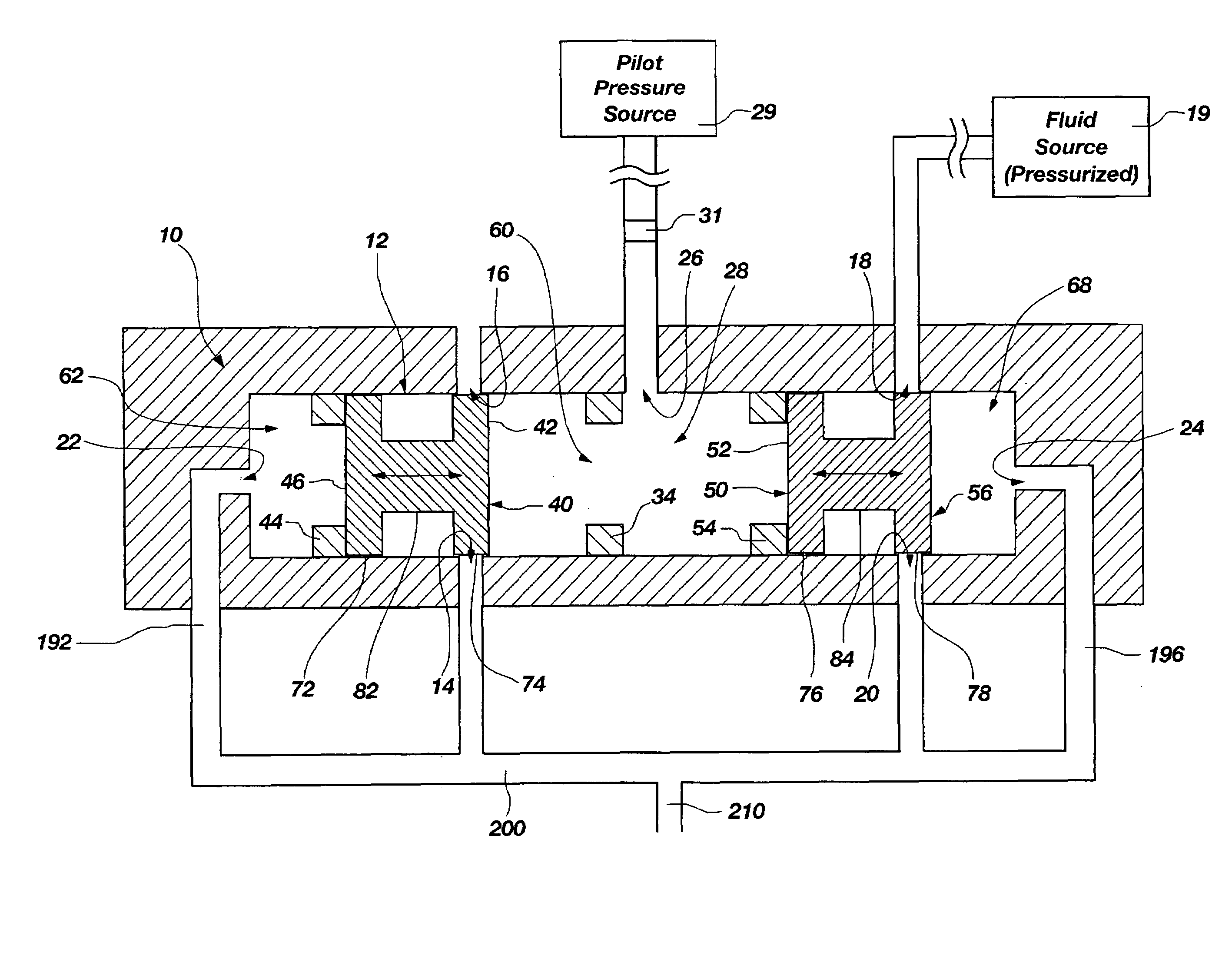
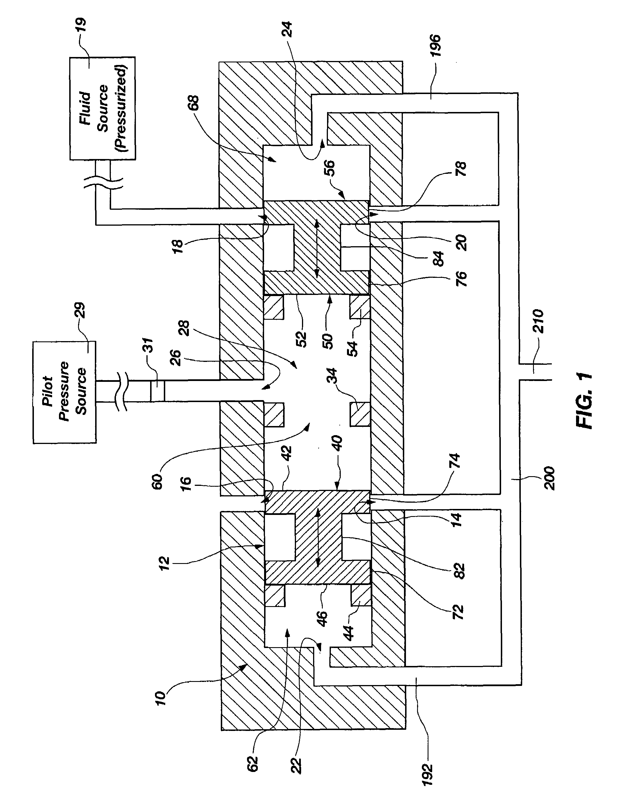
[0032]The following detailed description of exemplary embodiments of the invention makes reference to the accompanying drawings, which form a part hereof and in which are shown, by way of illustration, exemplary embodiments in which the invention may be practiced. While these exemplary embodiments are described in sufficient detail to enable those skilled in the art practice the invention, it should be understood that other embodiments may be realized and that various changes to the invention may be made without departing from the spirit and scope of the present invention. Thus, the following more detailed description of the embodiments of the present invention, as represented in FIGS. 1 through 9, is not intended to limit the scope of the invention, as claimed, but is presented for purposes of illustration only and not limitation to describe the features and characteristics of the present invention, to set forth the best mode of operation of the invention, and to sufficiently enabl...


PUM


Abstract

A method and system for controlling the dynamics of an actuatable load operable within a servo or servo-type system, wherein the dynamics of the load are controlled by way of a unique pressure control valve configured to provide intrinsic pressure regulation, thus eliminating the need for electronically or mechanically user controlled systems. The pressure control valve, which may be referred to as a dynamic pressure regulator, utilizes dual spools that are physically independent of one another and freely supported in the valve body to regulate the pressures acting within the overall system between the control or pilot pressure and the load or load pressure. The dual spools function in cooperation with one another to maintain a state of equilibrium in the system, namely to keep pressure acting on or within the actuator (the load pressure), or the feedback pressure corresponding to the load pressure, the same as the pilot pressure.

Description

RELATED APPLICATIONS[0001]This application claims priority to U.S. Provisional Patent Application No. 60 / 633,001 filed Dec. 2, 2004 in the United States Patent and Trademark Office, and entitled, “Pressure Control Valve Having Intrinsic Feedback System,” which application is incorporated by reference in its entirety herein.FIELD OF THE INVENTION[0002]The present invention relates to servo or servo-type valves configured to control or regulate fluid flow and / or pressure within a servo or other control system, and more particularly to a pressure control valve having an intrinsic feedback system, wherein the pressure control valve is configured with dual independent spool valves operating to regulate fluid flow, and more importantly pressure, within an open or closed loop system, and particularly between a control or pilot pressure source and a load pressure source.BACKGROUND OF THE INVENTION AND RELATED ART[0003]Control and servo systems, such as hydraulic or pneumatic systems, are we...

Claims


Application Information

Patent Timeline
Patent Type & Authority Patents(United States)
IPC IPC(8): F15B13/04
CPCF15B13/04F15B21/12F15B2211/76F15B2211/524F15B2211/565F15B2211/50554
Inventor JACOBSEN, STEPHEN C.OLSEN, SHANEMORRISON, MICHAEL
Owner SARCOS LC
Why Eureka
Try Eureka