
Interface device and method for interfacing instruments to vascular access simulation systems

Inactive Publication Date: 2007-12-18
IMMERSION MEDICAL
View PDF46 Cites 91 Cited by
  • Summary
  • Abstract
  • Description
  • Claims
  • Application Information

AI Technical Summary

Benefits of technology

[0015]Accordingly, it is an object of the present invention to enhance realism within a medical procedure simulation system by interfacing various peripherals in the form of mock medical instruments to the medical procedure simulation system via an interface device to enable realistic simulation of various aspects of a medical procedure.
[0016]It is another object of the present invention to facilitate simulation of vascular access procedures via an interface device to provide realistic training of these procedures to medical practitioners.
[0017]Yet another object of the present invention to provide enhanced training of a medical procedure to medical practitioners by enabling the medical practitioner to simulate manipulation and preparation of an anatomical site where the procedure is performed.
[0018]Still another object of the present invention is to enhance realism within a medical procedure simulation system and to provide enhanced training of a medical procedure to practitioners by interfacing plural vascular access instruments (e.g., needle and catheter assembly) to the medical procedure simulation system via an interface device to enable realistic simulation of a vascular access and / or catheterization procedure.
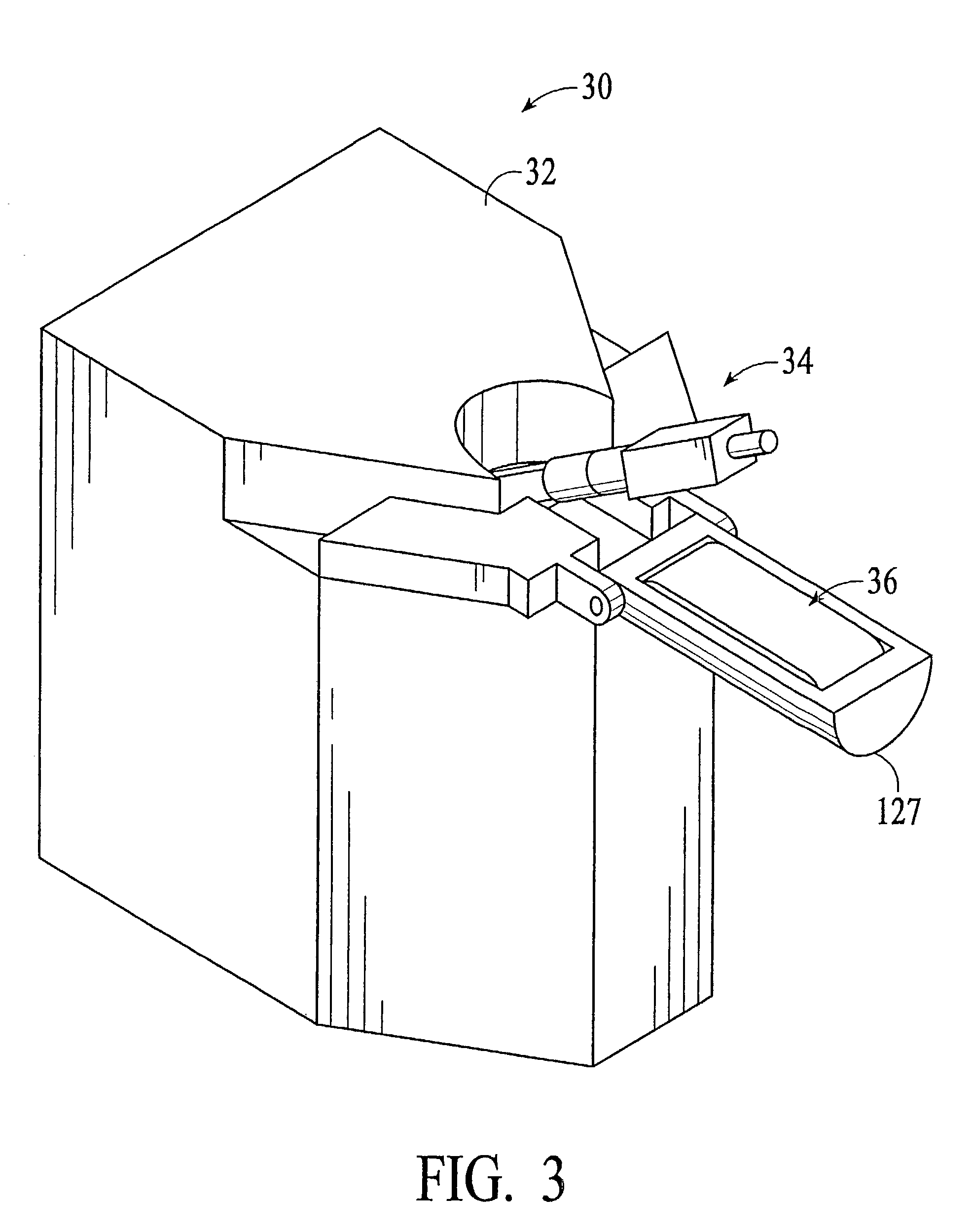
[0021]According to the present invention, an interface device and method for interfacing instruments to a vascular access simulation system, typically including a computer system and display, serve to interface peripherals in the form of mock or actual medical instruments to the simulation system to enable simulation of medical procedures. The interface device includes a catheter unit assembly for receiving a catheter needle assembly, and a skin traction mechanism to simulate manipulation of an anatomical site. The catheter needle assembly and skin traction mechanism are manipulated by a user during a medical procedure. The catheter unit assembly includes a base, a housing, a bearing assembly and a shaft that receives the catheter needle assembly. The housing is rotatably coupled to the base, while the bearing assembly is rotatably coupled to the housing, thereby enabling manipulation of the catheter needle assembly in two degrees of freedom (e.g., yaw and pitch, respectively). The bearing assembly enables translation of the catheter needle assembly, and includes bearings that enable the shaft to translate in accordance with manipulation of the catheter needle assembly. The shaft is coupled to a tension member that extends between the shaft proximal and distal ends, and about a pulley disposed between those ends. The tension member and pulley arrangement enables smooth motion of the catheter needle assembly. A force feedback device may be utilized to impede pulley rotation and apply force feedback to the catheter needle assembly.

Problems solved by technology

Although practicing medical procedures on live patients provides excellent training, a procedure may usually only be performed a limited number of times on a particular live patient, and may require the presence of a skilled practitioner to supervise and oversee the procedure to avoid injury to the patient.
Further, training medical professionals in medical procedures on live patients requires the use of proper facilities and equipment (e.g., hospital facilities and equipment), thereby incurring substantial costs and limiting procedure practice to a particular time and location.
Specifically, these systems utilize a physical model, thereby restricting training of a medical procedure to a particular bodily region or arterial paths defined by that model.
Further, use of physical models degrades realism of the simulation and reduces the benefits of simulation training since the models usually do not contain substantially the same complex anatomy as an actual body, and permit a physician or other medical professional to become accustomed to performing a procedure on the same model anatomy.
Performance of the procedure on another bodily region or through different arterial paths within the Hon and Saliterman systems typically requires a new model or substantial modifications to an existing model, thereby limiting flexibility of the systems and increasing system costs.
Moreover, the Saliterman system does not provide computer-controlled force feedback to an instrument, thereby degrading realism of the simulation and reducing the benefits of simulation training.
In other words, the Saliterman system does not provide a computer simulated feel of forces applied to an instrument during an actual medical procedure.
However, these systems do not provide a manner in which to simulate manipulation and preparation of an anatomical site where the procedure is performed, thereby limiting simulation and training to a portion of the medical procedure.
Further, the instruments interfacing the virtual reality systems typically extend into an interface device force reflective mechanism (e.g., having actuators), or extend through an interface device and interface numerous components, thereby possibly causing the instrument translational motion to be jerky or inconsistent during manipulation.
In addition, the Jacobus and Rosenberg (U.S. Pat. No. 5,623,582) systems generally employ a plurality of actuators to provide force feedback to a single instrument, thereby increasing system complexity and cost.
However, this interface device does not resemble a common medical instrument and does not provide a manner to apply computer controlled force feedback to the interface device, thereby degrading realism of a simulation and reducing benefits of simulation training.

Method used


Image

  • Interface device and method for interfacing instruments to vascular access simulation systems
  • Interface device and method for interfacing instruments to vascular access simulation systems
  • Interface device and method for interfacing instruments to vascular access simulation systems

Examples


Embodiment Construction

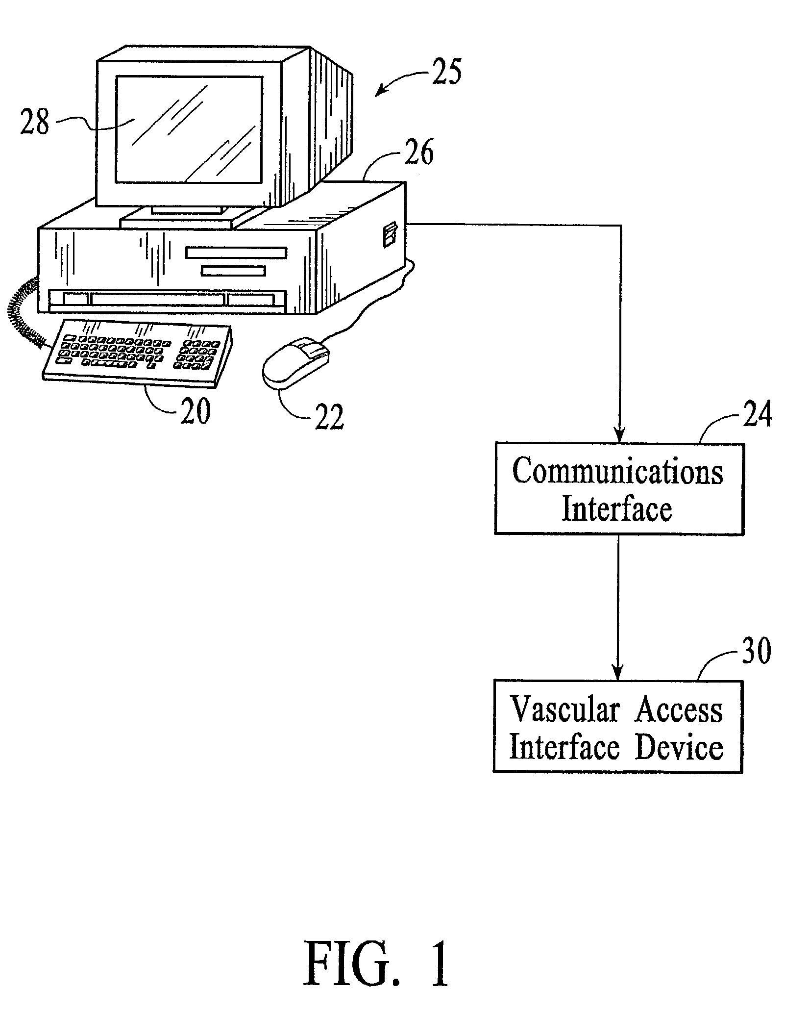
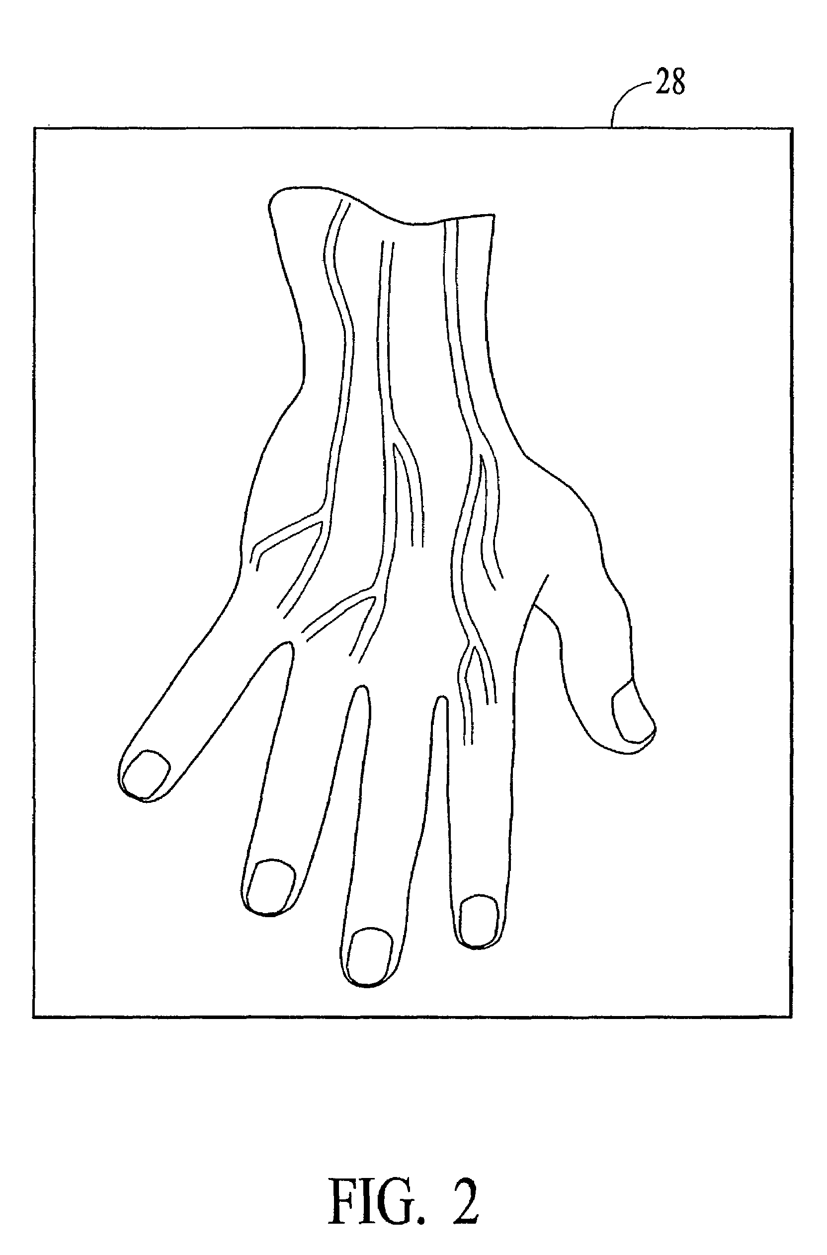
[0034]A vascular access training system for training medical professionals to access veins is illustrated in FIGS. 1-2. The vascular access training system trains medical professionals to access veins in hospital and / or clinical settings for introduction of fluids into and sampling blood from the accessed veins. Basically, the vascular access training system may be utilized to train medical professionals to perform various techniques, such as peripheral vascular access, intravenous catheterization, peripherally inserted central catheter placement and central venous catheterization. Specifically, the vascular access training system includes a computer system 25, an interface device 30 and communications interface 24 for transferring signals between computer system 25 and interface device 30. Computer system 25 includes a monitor 28, base 26 (e.g., including processor(s), memories and accompanying hardware), keyboard 20 and mouse 22, and is typically implemented by a conventional or c...


PUM


Abstract

An interface device and method for interfacing instruments to a vascular access simulation system serve to interface peripherals in the form of mock or actual medical instruments to the simulation system to enable simulation of medical procedures. The interface device includes a catheter unit assembly for receiving a catheter needle assembly, and a skin traction mechanism to simulate placing skin in traction or manipulating other anatomical sites for performing a medical procedure. The catheter needle assembly and skin traction mechanism are manipulated by a user during a medical procedure. The catheter unit assembly includes a base, a housing, a bearing assembly and a shaft that receives the catheter needle assembly. The bearing assembly enables translation of the catheter needle assembly, and includes bearings that enable the shaft to translate in accordance with manipulation of the catheter needle assembly. The shaft typically includes an encoder to measure translational motion of a needle of the catheter needle assembly, while the interface device further includes encoders to measure manipulation of the catheter needle assembly in various degrees of freedom (e.g., translation, pitch and yaw) and the skin traction mechanism. Alternatively, the shaft may include an additional encoder to measure translational motion of an instrument inserted through the catheter needle assembly. The simulation system receives measurements from the interface device encoders and updates the simulation and display, while providing control signals to the force feedback device to enable application of force feedback to the catheter needle assembly.

Description

CROSS-REFERENCE TO RELATED APPLICATIONS[0001]This application is a continuation application of application Ser. No. 09 / 238,559, filed Jan. 28, 1999, now U.S. Pat. No. 6,470,302, which claims the benefit of Provisional Application Ser. No. 60 / 072,809, filed Jan. 28, 1998, the disclosures of each of which are incorporated herein by reference in their entirety.BACKGROUND OF THE INVENTION[0002]1. Technical Field[0003]The present invention pertains to computerized simulation systems, generally of the types disclosed in: International Publication Number WO 96 / 28800, published Sep. 19, 1996 and entitled “Computer Based Medical Procedure Simulation System”; U.S. patent application Ser. No. 08 / 923,477, filed Sep. 4, 1997 and entitled “Interventional Radiology Interface Apparatus and Method”; and U.S. Patent Application Docket No. C0136.HTM, filed Jan. 27, 1999 and entitled “Interface Device and Method for Interfacing Instruments to Medical Procedure Simulation Systems”. The disclosures of th...

Claims


Application Information

Patent Timeline
IPC IPC(8): G01N3/24A61M1/02G09B9/00A61M5/00G06Q50/00G09B23/28
CPCG09B23/28G09B23/30G09B23/285
Inventor CUNNINGHAM, RICHARD L.FELDMAN, PHILIPFELDMAN, BENMERRIL, GREGORY L.
Owner IMMERSION MEDICAL
Learn More