
Visual, operable and non-solid touch screen system

A touch screen and virtual touch technology, applied in the field of human-computer interaction, can solve the problems of not considering how the user observes the virtual output, not realizing virtualization, unnatural use, etc.

Inactive Publication Date: 2010-03-17
FUDAN UNIV
View PDF1 Cites 76 Cited by
  • Summary
  • Abstract
  • Description
  • Claims
  • Application Information

AI Technical Summary

Problems solved by technology

However, they have a common disadvantage: using unnatural
This invention can solve the problem of using direct human input, but it does not take into account how the user observes the virtual output, but uses an ordinary display screen for output, and does not realize virtualization at the output level

Method used

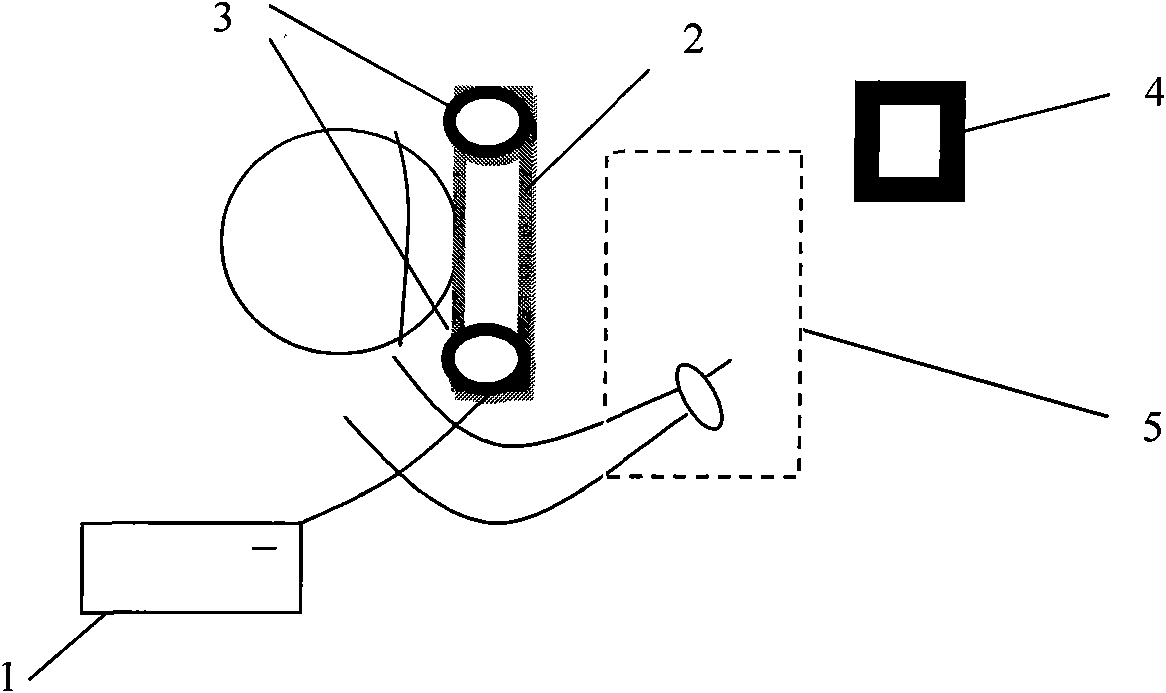
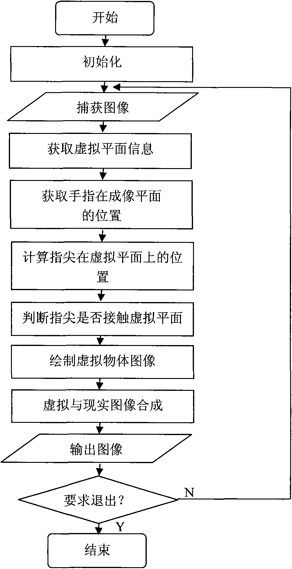

Image

  • Visual, operable and non-solid touch screen system
  • Visual, operable and non-solid touch screen system
  • Visual, operable and non-solid touch screen system

Examples


Embodiment 1

[0086] Embodiment 1: Realize the operation of Windows programs on the virtual touch screen as an example.

[0087] This embodiment shows how the present invention can replace a common touch screen to operate a computer.

[0088] When using, the user wears the head-mounted display and the two network cameras fixed on it, and places the calibration reference object at the same time. After running the system on the computer, the user can see a virtual touch screen appearing next to the calibration reference object through the head-mounted display, with the interface of the Windows program on it. When the user clicks on the virtual touch screen with the index finger, the touch screen will perform corresponding operations. For example, when the user presses the icon with the index finger and then lifts it up to complete a click operation, the icon is selected; when the user presses the icon, the fingertip remains on the plane of the virtual touch screen and moves, and the icon wil...

Embodiment 2

[0113] Embodiment 2: Multi-touch photo browsing on the virtual touch screen

[0114] This example shows the multi-touch function of the present invention.

[0115] After the user wears the device and starts up the computer system, he can see multiple photos displayed on the virtual touch screen. When the user drags the center of the photo left and right with the index finger of the right hand, the photo will be switched; when the user drags the upper left and lower right corners of the photo with the index fingers of the left and right hands at the same time, the photo will be zoomed according to the positions of the two fingers.

[0116] In the implementation of this example, when performing fingertip recognition, the two largest and second largest connected regions are taken as the hand region, and the fingertip on the left side of the plane is considered to be the left fingertip, and the fingertip on the right side of the plane is the right fingertip.

[0117] For each pho...


PUM


Abstract

The invention belongs to the technical field of human-computer interaction, and is a visual, operable and non-solid touch screen system which comprises a computer, two network cameras, a head-mounteddisplay and a calibration reference object, wherein the calibration reference object calibrates a virtual touch screen. A user can observe a real world containing the virtual touch screen, and directly operates the non-solid touch screen by hand through the head-mounted display. The invention uses two cameras for real-time image collection. The computer system carries out spatial calibration and the identification of the action of fingertip positions according to the image input by the cameras and synthesizes a corresponding image. The head-mounted display outputs the image containing the virtual touch screen to the user, and the user directly observes the feedback of the virtual touch screen through the head-mounted display. The invention can be used in the field of human-computer interaction, and is particularly suitable to be used as the equipment of human-computer interaction of a portable computer or a multimedia interaction experience system.

Description

technical field [0001] The invention belongs to the technical field of human-computer interaction, and in particular relates to a visual and operable touch screen system. Background technique [0002] In many virtual reality systems, users use data gloves, stylus, and three-dimensional mouse to operate instead of mouse and keyboard. They can adapt to the requirements of spatial positioning in the virtual reality system and expand the form of operation. However, they have a common disadvantage: unnatural use. When users use these devices, some have to wear heavy equipment, and some have to be connected to data cables that limit the range of motion. [0003] The anthropomorphism of computer systems represented by virtual reality and the miniaturization, portability, and embedding of computers represented by handheld computers and smart phones are two important development trends of current computers. The GUI technology is the bottleneck affecting their development. Therefo...

Claims


Application Information

Patent Timeline
IPC IPC(8): G06F3/042G06F3/01
Inventor 许景禧沈一帆
Owner FUDAN UNIV
Learn More