
Combustor and method of improving manufacturing accuracy thereof

a technology of combustion engines and combustion chambers, which is applied in the direction of combustion process, hot gas positive displacement engine plants, lighting and heating apparatus, etc., can solve the problem that the design of large-scale designs cannot be simply scaled down, and achieve the effect of improving the overall manufacturing tolerance of said drilling and improving the manufacturing accuracy of heat shieldless

Active Publication Date: 2007-12-18
PRATT & WHITNEY CANADA CORP
View PDF44 Cites 17 Cited by
  • Summary
  • Abstract
  • Description
  • Claims
  • Application Information

AI Technical Summary

Benefits of technology

[0004]In accordance with another aspect there is also provided a method a method of improving manufacturing accuracy of a heat shieldless annular reverse flow combustor, the method comprising the steps of providing a annular reverse flow combustor with an end dome adapted for receiving a fuel nozzle; maximizing a flat area of the end dome, the flat area disposed generally perpendicularly to a combustor axis; and drilling a plurality of effusion cooling holes in the flat area of the dome, to thereby improve the overall manufacturing tolerances of said drilling.

Problems solved by technology

Also, a new generation of very small gas turbine engines is emerging (i.e. a fan diameter of 20 inches or less, with about 2500 lbs. thrust or less), however larger designs cannot simply be scaled-down, since many physical parameters do not scale linearly, or at all, with size (droplet size, drag coefficients, manufacturing tolerances, etc.).

Method used


Image

  • Combustor and method of improving manufacturing accuracy thereof
  • Combustor and method of improving manufacturing accuracy thereof
  • Combustor and method of improving manufacturing accuracy thereof

Examples


Embodiment Construction

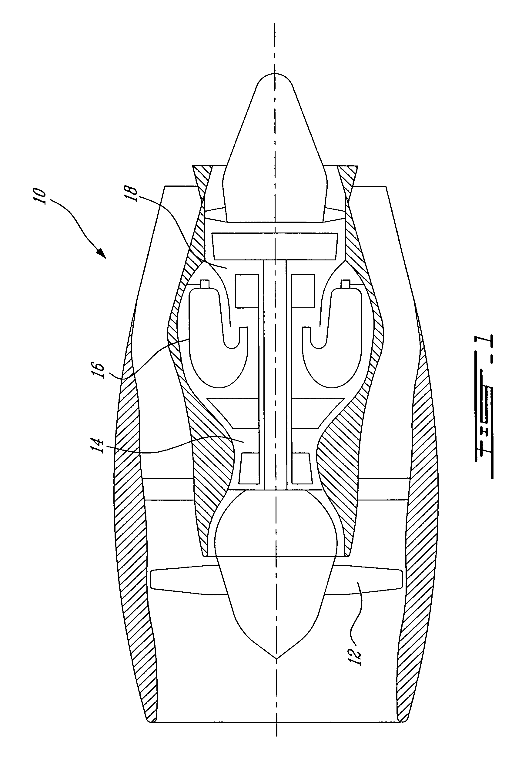
[0011]FIG. 1 illustrates a gas turbine engine 10 preferably of a type provided for use in subsonic flight, generally comprising in serial flow communication a fan 12 through which ambient air is propelled, a multistage compressor 14 for pressurizing the air, an annular combustor 16 in which compressed air is mixed with fuel and ignited for generating an annular stream of hot combustion gases which is then redirected by combustor 16 to a turbine section 18 for extracting energy from the combustion gases.

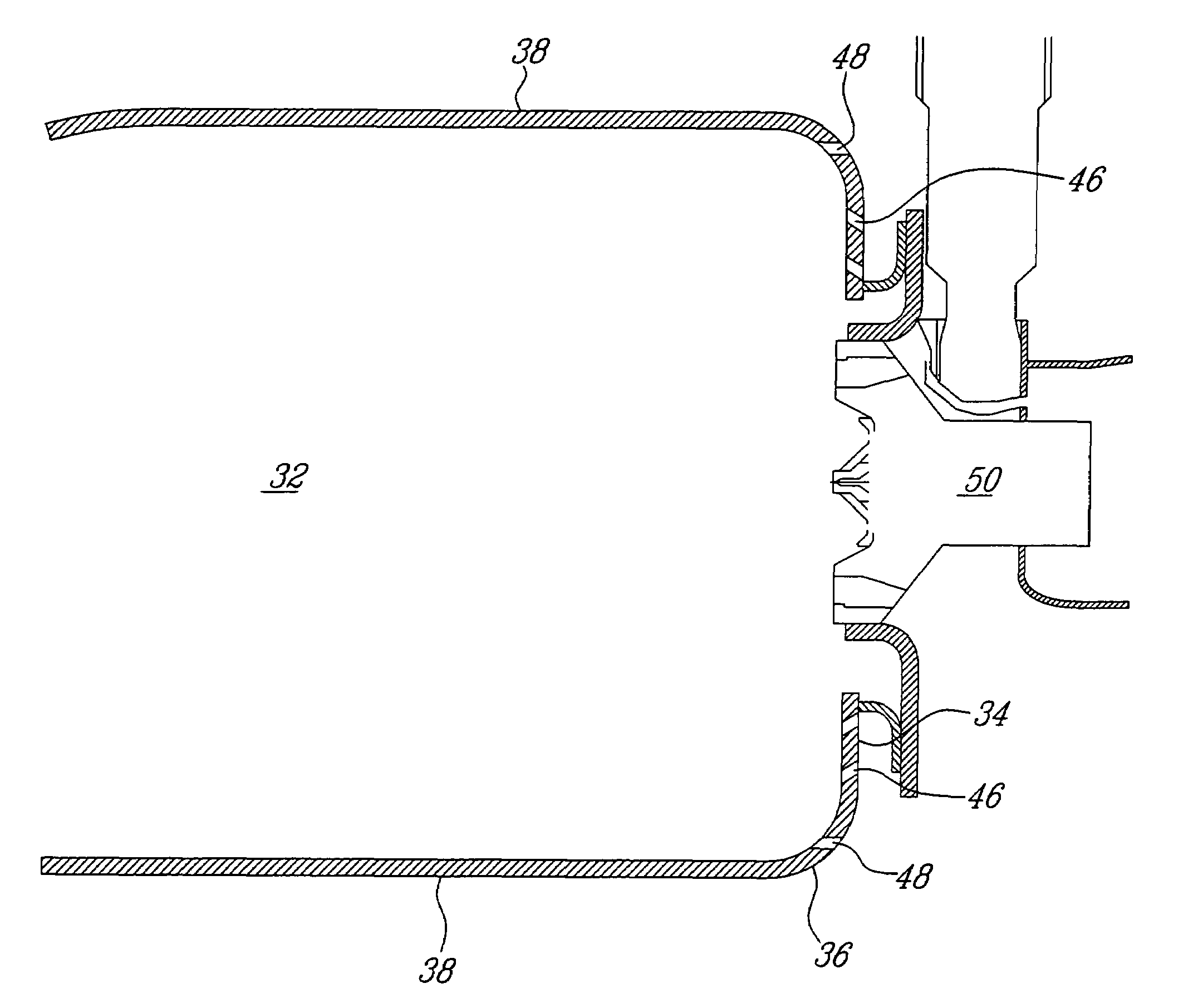
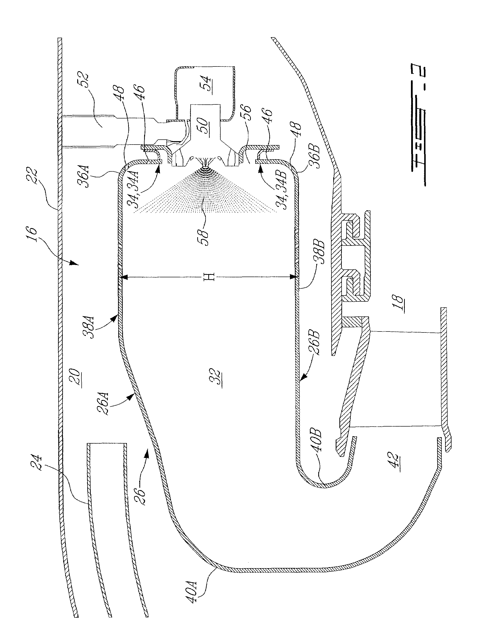
[0012]Referring to FIG. 2, the combustor 16 is housed in a plenum 20 defined partially by a gas generator case 22 and supplied with compressed air from compressor 14 by a diffuser 24. Combustor 16 comprises generally a liner 26 composed of an outer liner 26A and an inner liner 26B defining a combustion chamber 32 therein. Combustor 16 preferably has a generally flat dome 34, as will be described in more detail below. Outer liner 26A includes a outer dome panel portion 34A, a relativel...


PUM


Abstract

An improved gas turbine engine combustor with a liner and a dome connected to the liner trough small radius transition portions only, the dome having a plurality of fuel nozzles mounted therein and an interior directly exposed to a combustion region of the combustor, the dome including a plurality of effusion cooling holes provided non-perpendicularly to an entry surface of the holes, the dome being substantially planar.

Description

TECHNICAL FIELD[0001]The present invention relates generally to gas turbine engine combustors and, more particularly, to a low cost combustor configuration having improved performance.BACKGROUND OF THE ART[0002]Gas turbine combustors are the subject of continual improvement, to provide better cooling, better mixing, better fuel efficiency, better performance, etc. at a lower cost. Also, a new generation of very small gas turbine engines is emerging (i.e. a fan diameter of 20 inches or less, with about 2500 lbs. thrust or less), however larger designs cannot simply be scaled-down, since many physical parameters do not scale linearly, or at all, with size (droplet size, drag coefficients, manufacturing tolerances, etc.). There is, therefore, a continuing need for improvements in gas turbine combustor design.SUMMARY OF THE INVENTION[0003]In accordance with the present invention there is provided a gas turbine engine combustor comprising a liner defining an annular reverse-flow configur...

Claims


Application Information

Patent Timeline
Patent Type & Authority Patents(United States)
IPC IPC(8): F02C1/00
CPCF23R3/10F23R3/54F23R2900/03041
Inventor MORENKO, OLEGPATEL, BHAWAN BHAI
Owner PRATT & WHITNEY CANADA CORP
Learn More