
Fusion night vision system

a night vision and fusion technology, applied in the field of night vision devices, can solve the problems of not having sufficient resolution and sensitivity to provide acceptable scene imagery, and inability to see a person hidden under camouflage, and achieve the effect of reducing the gain of an image intensification tub

Active Publication Date: 2007-12-11
L 3 COMMUNICATIONS INSIGHT TECHNOLOGY INCORPORATED
View PDF38 Cites 56 Cited by
  • Summary
  • Abstract
  • Description
  • Claims
  • Application Information

AI Technical Summary

Benefits of technology

[0024]According to a yet a further aspect of the invention, there is provided a method of locating a target with a fusion night vision system having automatic gain control of a thermal channel and an image intensification tube, the method includes receiving an enter targeting mode signal, reducing the gain of an image intensification tube, and leaving the automatic gain of the thermal channel enabled.

Problems solved by technology

A drawback to night vision goggles is that they cannot see through smoke and heavy sand storms and cannot see a person hidden under camouflage.
One advantage of infrared sensors is that they are less attenuated by smoke and dust and a drawback is that they typically do not have sufficient resolution and sensitivity to provide acceptable imagery of the scene.
A problem with the optically fused system 200 is that two separate potentiometers must be adjusted to control the mix of I2 and thermal information in the fused image and there is no independent control of the perceived brightness of the fused image.
At distances different from the predetermined distance, parallax can cause a misalignment of the two images in the eyepiece.
The parallax problem exists if the thermal channel and the I2 channels are offset in the horizontal as well as the vertical directions.
Depending on the location of a target and its surroundings, information from the thermal channel can obscure the information from the image intensification channel and make it more difficult to acquire and identify a target.
A heavier system that has a center of gravity far from the soldier's head results in discomfort and neck strain to the user.
The drawback to these systems is that the resolution of the digitized imagery is reduced typically by a factor of two, which is often insufficient for most military applications.

Method used


Image

  • Fusion night vision system
  • Fusion night vision system
  • Fusion night vision system

Examples


Embodiment Construction

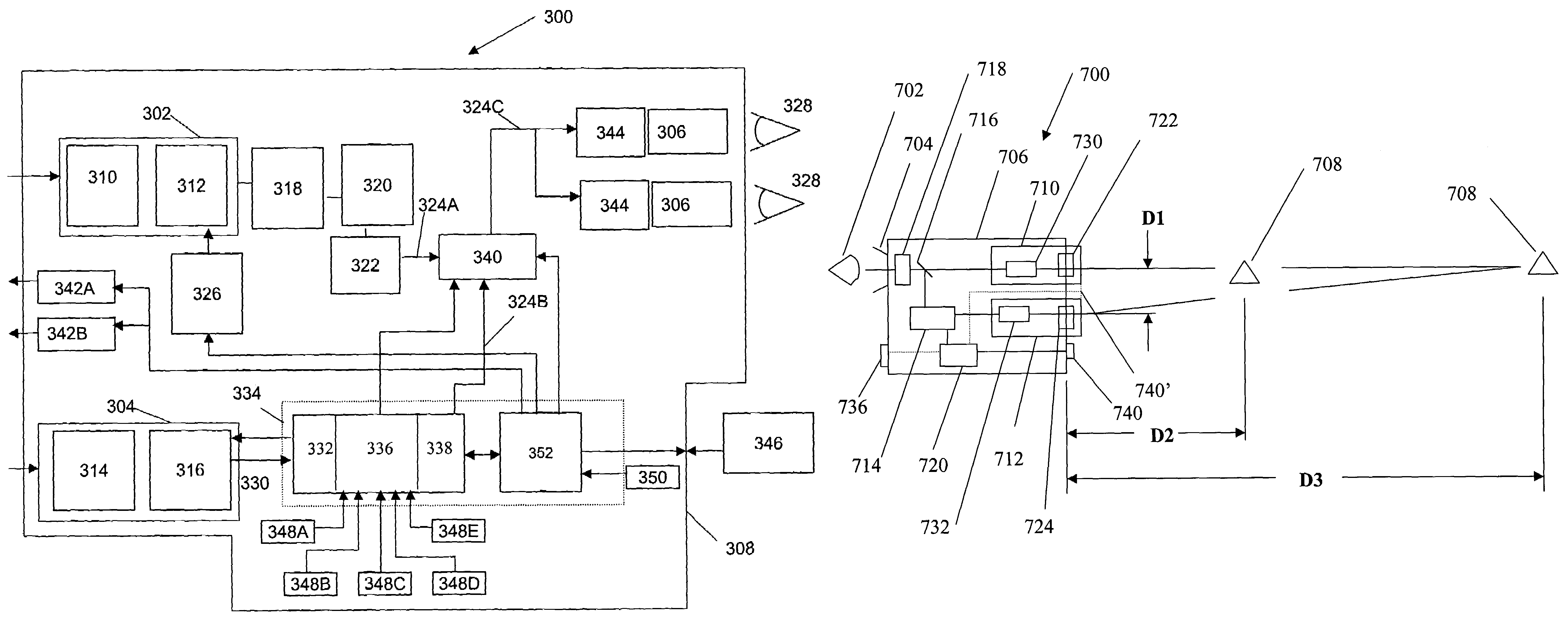
[0053]FIG. 3 is a block diagram of a first fusion night vision system 300. The electronics and optics may be housed in a housing 308. Information from a first channel (I2) channel 302 and a second channel 304 may be fused together for viewing by an operator 328. A channel may be an optical path through which scene information may travel. The first channel 302 may be configured to process information in a first range of wavelengths (the visible portion of the electromagnetic spectrum from approximately 400 nm to approximately 900 nm) and the second channel 304 may be configured to process information in a second range of wavelengths (from approximately 7,000 nm to approximately 14,000 nm). The low end and the high end of the range of wavelengths may vary without departing from the invention. The first channel 302 may have an objective focus 310 and an image intensification (I2) tube 312. Suitable I2 tubes 312 may be Generation III tubes and are available from Northrop Grumman and ITT...


PUM


Abstract

A fusion night vision system having image intensification and thermal imaging capabilities includes an edge detection filter circuit to aid in acquiring and identifying targets. An outline of the thermal image is generated and combined with the image intensification image without obscuration of the image intensification image. The fusion night vision system may also include a parallax compensation circuit to overcome parallax problems as a result of the image intensification channel being spaced from the thermal channel. The fusion night vision system may also include a control circuit configured to maintain a perceived brightness through an eyepiece over a mix of image intensification information and thermal information. The fusion night vision system may incorporate a targeting mode that allows an operator to acquire a target without having the scene saturated by a laser pointer. The night vision system may also include a detector, an image combiner for forming a fused image from the detector and a display, and a camera aligned with image combiner for recording scene information processed by the first detector.

Description

CROSS REFERENCE TO RELATED APPLICATIONS[0001]The present application claims the benefit of U.S. provisional patent application Ser. No. 60 / 585,327, filed Jul. 2, 2004; Ser. No. 60 / 589,693 filed Jul. 21, 2004, and Ser. No. 60 / 645,097, filed Jan. 20, 2005, the entire disclosures of which are incorporated herein by reference.TECHNICAL FIELD[0002]The invention is generally related to night vision devices and, more particularly, to systems and methods for improving the viewability and recordability of images through a night vision device.BACKGROUND OF THE INVENTION[0003]Night vision systems include image intensification, thermal imaging, and fusion monoculars, binoculars, and goggles, whether hand-held, weapon mounted, or helmet mounted. Standard night vision systems are typically equipped with one or more image intensifier tubes to allow an operator to see visible wavelengths of radiation (approximately 400 nm to approximately 900 nm). They work by collecting the tiny amounts of light, ...

Claims


Application Information

Patent Timeline
Patent Type & Authority Patents(United States)
IPC IPC(8): G02B27/14
CPCG01J5/02G01J5/0265G01J5/0275G01J5/08G01J5/0859G02B23/125G02B27/017G02B27/0172H04N5/33H04N5/332G01J5/025G02B2027/0132G01J2005/0077G02B2027/0118G02B2027/0129G02B2027/0138G02B2027/014H04N23/11H04N23/70
Inventor OTTNEY, JOSEPH C.HOHENBERGER, ROGER T.RUSSELL, ANDREW D.
Owner L 3 COMMUNICATIONS INSIGHT TECHNOLOGY INCORPORATED
Learn More