Optical image measuring apparatus and optical image measuring method
a technology of optical image and measuring apparatus, which is applied in the direction of instruments, measurement devices, interferometers, etc., can solve the problems of difficult shortening the measurement time in view of measurement fundamentals, difficult to actually use the apparatus in fields that require high resolution images, and reducing etc., to achieve the effect of improving the detection sensitivity of the first interference light, simplifying the structure of the apparatus and the control mod
- Summary
- Abstract
- Description
- Claims
- Application Information
AI Technical Summary
Benefits of technology
Problems solved by technology
Method used
Image
Examples
first embodiment
[Structure of Apparatus]
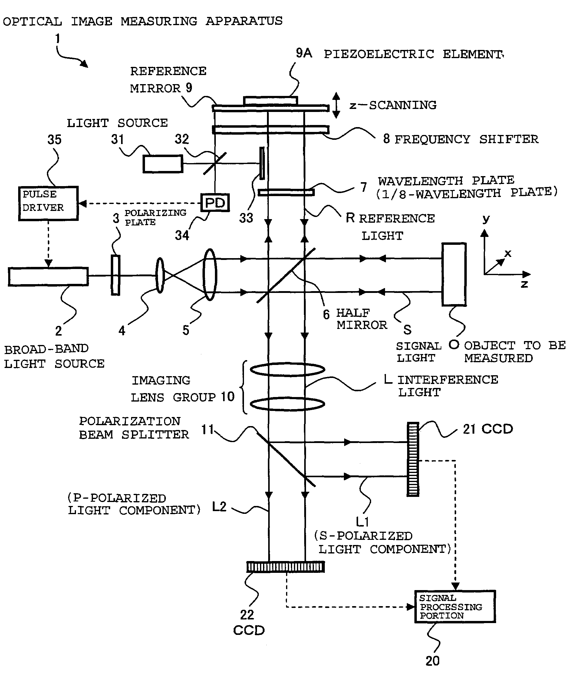
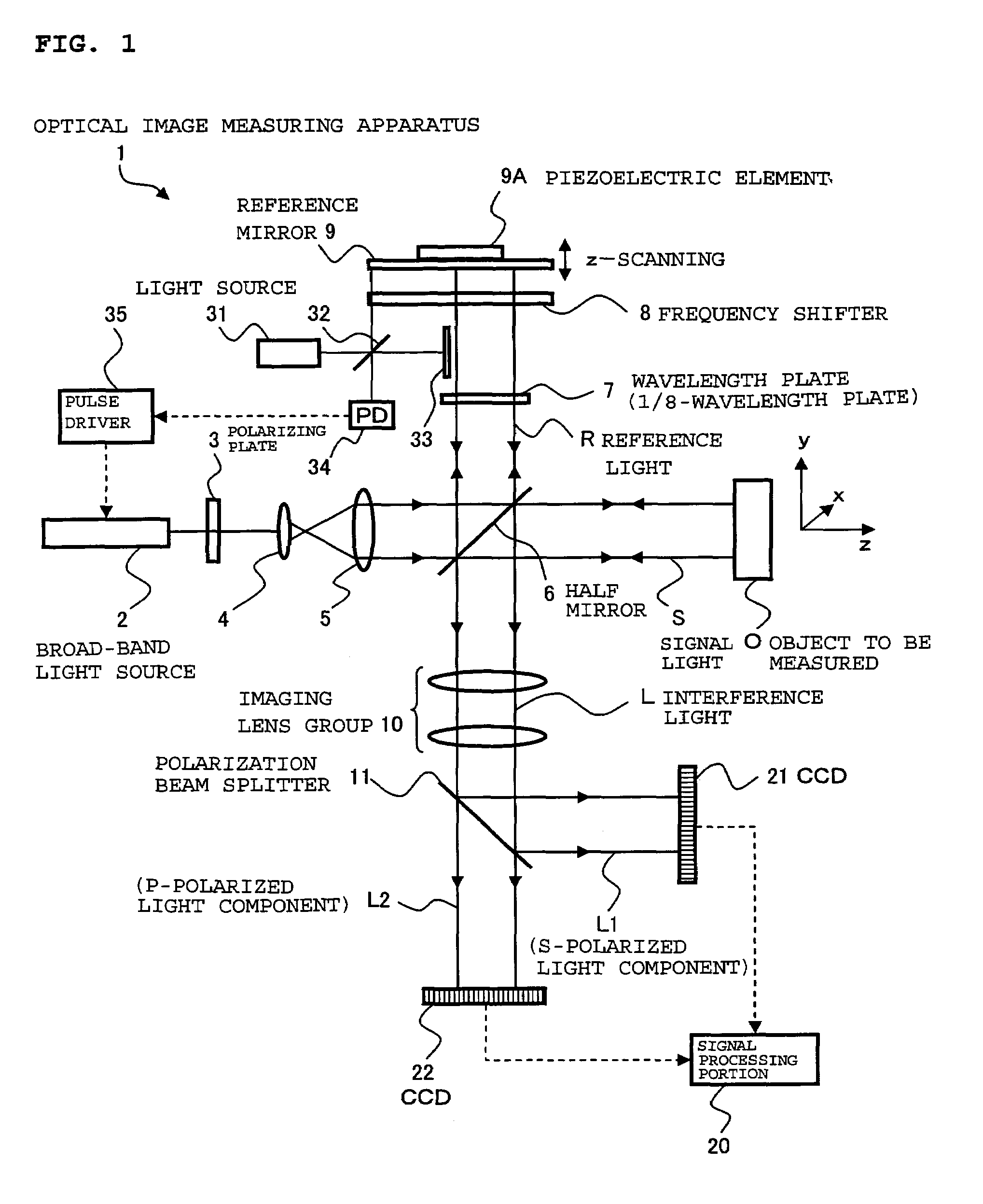
[0053]FIG. 1 shows a schematic structure of an optical image measuring apparatus 1 according to a first embodiment of the present invention. The optical image measuring apparatus 1 is an apparatus available to measure a sectional image and a surface image of an object to be measured O, for example, in the medical field and the industrial field. The object to be measured O is an object which is made of a scattering medium such as a human eye, for example, in the medical field.
[0054]The optical image measuring apparatus 1 includes a broad-band light source 2 for outputting a low-coherent light beam, a polarizing plate 3 for converting a polarization characteristic of the light beam to linear polarization, lenses 4 and 5 for converting the light beam to a parallel light flux and increasing a beam diameter thereof, and a half mirror 6 for dividing the light beam into signal light S and reference light R and also superimposing the signal light S and the reference ...
second embodiment
[0128]In the first embodiment described above, the frequency shifter 8 for applying optoelectronic frequency shift or acoustooptic frequency shift and the reference mirror 9 and the piezoelectric element 9A which are for applying Doppler frequency shift are used to shift the frequency of the reference light R. In contrast to this, in this embodiment, the frequency shift is provided only by the frequency shifter 8. The reference mirror 9 and the piezoelectric element 9A are used not for the application of Doppler frequency shift to the reference light R but for scanning of the object to be measured O in the depth direction (z-scanning).
[0129]FIG. 4 shows a schematic structure of an optical image measuring apparatus 1′ according to a second embodiment of the present invention. The optical image measuring apparatus 1′ has substantially the same structure as that described in the first embodiment and includes a control portion 110 for detecting the amount of frequency shift applied by t...
PUM
 Abstract
Description
Claims
Application Information
 - R&D
- Intellectual Property
- Life Sciences
- Materials
- Tech Scout
- Unparalleled Data Quality
- Higher Quality Content
- 60% Fewer Hallucinations
Browse by: Latest US Patents, China's latest patents, Technical Efficacy Thesaurus, Application Domain, Technology Topic, Popular Technical Reports.
© 2025 PatSnap. All rights reserved.Legal|Privacy policy|Modern Slavery Act Transparency Statement|Sitemap|About US| Contact US: help@patsnap.com


