
Special fluids for use in a hydrostatic transmission

Inactive Publication Date: 2007-11-27
SAUER DANFOSS NORDBERG
View PDF18 Cites 21 Cited by
  • Summary
  • Abstract
  • Description
  • Claims
  • Application Information

AI Technical Summary

Benefits of technology

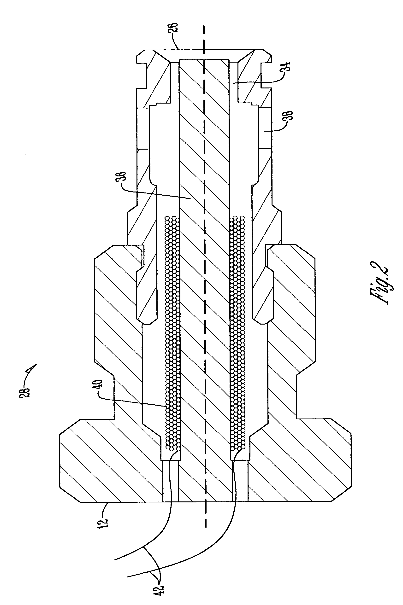
[0008]In one embodiment of the present invention, MR fluid is used as the active transmission fluid. Flow of the MR fluid through the cylinder is controlled by electromagnets located in close proximity to the intake and output ports of the cylinder. By energizing the electromagnet, the viscosity of the MR fluid can be increased such that the portion of the fluid immediately near the electromagnet substantially solidifies. The solidified portion of the MR fluid disables fluid through the particular passage, thereby restricting flow of the MR fluid to the cylinder.
[0009]In another embodiment of the present invention, ER fluid is used as the active transmission fluid. Flow of the ER fluid through the cylinder is controlled by electrodes located in close proximity to the intake and output ports of the cylinder. Just as with the MR fluid system, energizing the electrode can substantially solidify the portion of the ER fluid near the electrode, effectively disabling the flow of the ER fluid through the particular passage.

Problems solved by technology

One disadvantage of the mechanical valves used to control the flow of transmission fluid through cylinders of conventional piston pumps is that they comprise many moving parts.
Typical check valves include moving poppets and springs, all of which add to the cost of the piston pump.
Further, these components can degrade over time, causing inefficient pump performance or failure.
Stangroom does not, however, teach the use of MR and ER fluids as transmission fluids.

Method used


Image

  • Special fluids for use in a hydrostatic transmission
  • Special fluids for use in a hydrostatic transmission
  • Special fluids for use in a hydrostatic transmission

Examples


Embodiment Construction

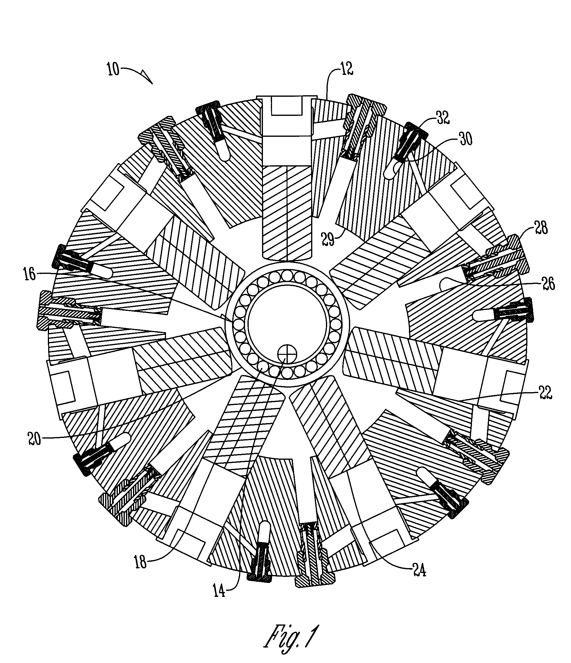
[0015]With respect to FIG. 1, a positive displacement piston unit 10 is shown adapted for use with MR transmission fluid. It should also be noted that the piston unit 10 may be a hydraulic pump or a motor. As shown in FIG. 1, the piston pump 10 may be arranged in a radial configuration. Alternatively, the piston pump 10 may be arranged in an axial or bent axis configuration, as is common in the art.

[0016]The piston pump 10 includes a housing 12 and a drive shaft 14. A bearing 16 is eccentrically mounted on shaft 14 and includes rolling elements 18 retained within an outer race 20. Bearing 16 is an antifriction bearing such as a ball bearing or a roller bearing, and rolling elements 18 comprise ball bearings or rollers. Housing 12 includes a plurality of bores 22. Cylinder pistons 24 fit within the bores 22 and ride against the outer race 20 of bearing 16. As the pump shaft 14 rotates, the eccentric bearing 16 gyrates about shaft 14, causing the pistons 24 to reciprocate in and out o...


PUM


Abstract

A positive displacement piston unit is provided that utilizes a magnetorheological (MR) or electrorheological (ER) fluid as the transmission fluid. Each cylinder of the invention has an intake port connected to the suction port of the hydrostatic pump and an output port connected to the pressure port. Flow of the transmission fluid through the cylinder is controlled by an electromagnet or electrode located in close proximity to the intake and output ports of the cylinder. By energizing the electromagnet or electrode, the viscosity of the transmission fluid can be increased such that the portion of the fluid immediately near the electromagnet or electrode substantially solidifies. The solidified portion of the transmission fluid disables fluid through the particular passage, thereby restricting flow of the transmission fluid to the cylinder. As such, the present invention does not require the use of mechanical cylinder valves to control the flow of the transmission fluid.

Description

BACKGROUND OF THE INVENTION[0001]Positive displacement piston pumps are well known in the art. Typically, piston pumps are comprised of a plurality of cylinders containing pistons that travel in and out of the cylinder bores. The cylinders are in fluid communication with the pump's intake or suction port as well as the pump's output or pressure port. The cylinders have mechanical valving to enable or disable the flow from either the pump's suction or pressure ports. Two types of mechanical valving are well known in positive displacement piston pumps. An example of the first type of mechanical valving is a valve plate which will enable the required timing of fluid communication as a cylinder block rotates. The second type of mechanical valving comprises check valves. In a positive displacement piston pump utilizing check valves, the check valves alternately open and close to allow fluid into and out of the piston bores, as the pistons reciprocate into and out of the cylinder bores, t...

Claims


Application Information

Patent Timeline
IPC IPC(8): F04B1/04F04B1/12
CPCF04B1/0452F04B53/1082F04B15/00F04B7/0076
Inventor GANDRUD, MICHAEL D
Owner SAUER DANFOSS NORDBERG
Learn More