
Ink tubing chain slider for wide format printer

a wide format printer and chain slider technology, applied in the direction of printing mechanism, spacing mechanism, printing, etc., can solve the problems of inaccuracy of drop placement and/or size, vibration and other positional deviation of the cartridge, and reduce image quality, so as to reduce the friction caused by the weight of the carriag

Inactive Publication Date: 2007-11-27
EASTMAN KODAK CO
View PDF3 Cites 2 Cited by
  • Summary
  • Abstract
  • Description
  • Claims
  • Application Information

AI Technical Summary

Benefits of technology

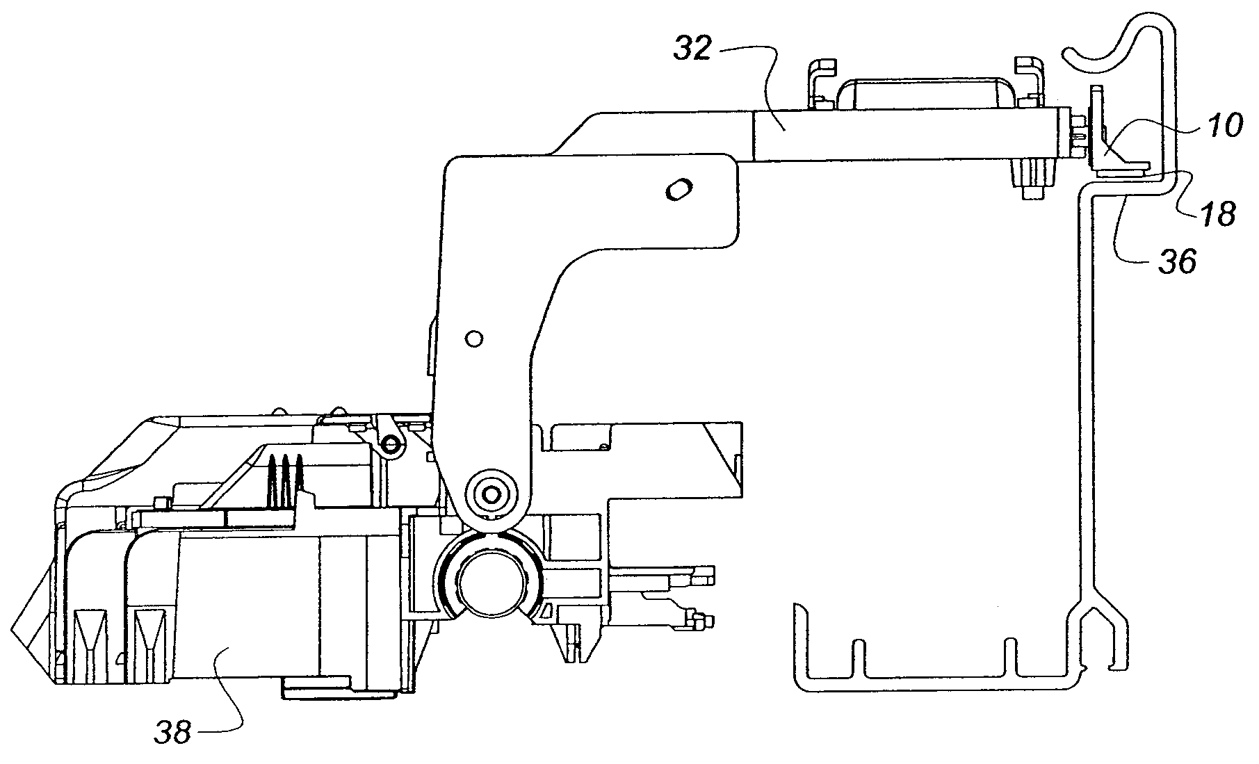
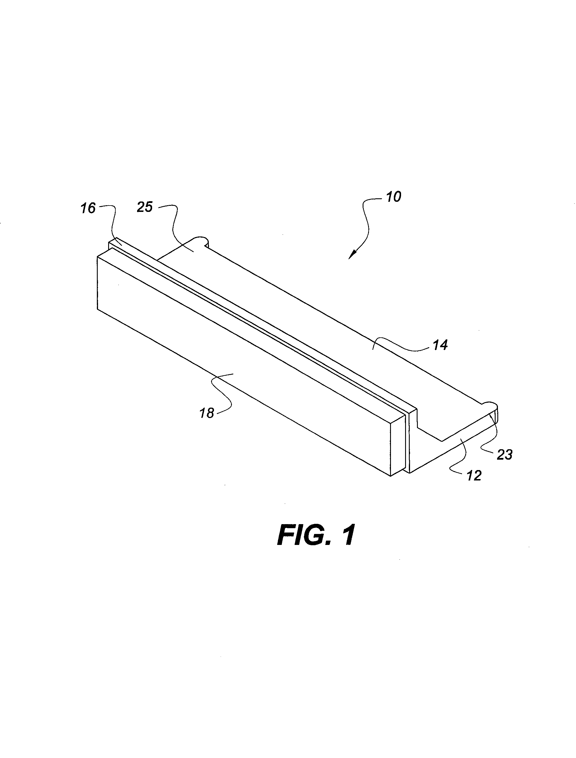
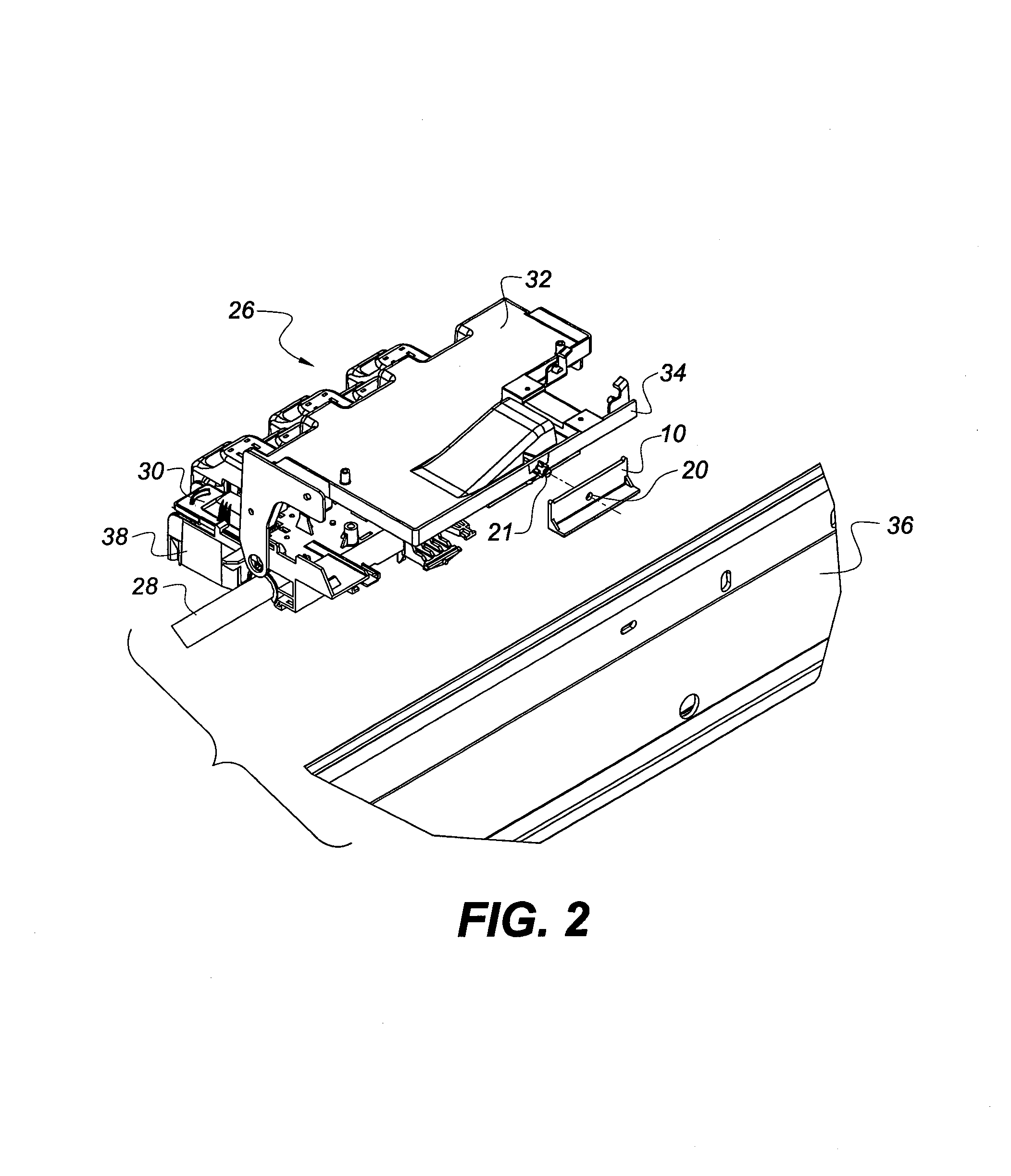
The patent describes a device for ink jet printers that reduces friction caused by the weight of the carriage. It includes a slider and a pin. The slider has a rigid substrate with two sides connected at an angle between 80 degrees and 100 degrees. It also has a hole in one of the sides and a fabric with extended fibers secured to the side without the hole. The fabric rests against a rear support wall of the printer and helps resist static charge accumulations. The pin is secured to the carriage and engages the hole. The pin allows the slider to rotate up to 360 degrees around the pin. The technical effect of this device is to improve the performance and reliability of ink jet printers by reducing friction and improving the movement of the carriage.

Problems solved by technology

Accordingly, any deviations in printhead position during printing (other than the desired printhead scanning motion across the media) can result in inaccurate drop placement and / or size, and thus reduce image quality.
External forces from the ink supply tubing can be transmitted to the carriage, causing vibrations and other positional deviations of the cartridges as they pass over the media.
Since this positional deviation is consistent with carriage location during a scan, print errors caused by this problem appear as visible vertical banding in the printed image.
The plastic slider is not an ideal solution because the slider is susceptible to defects on the surface of the part the slider is sliding against.

Method used


Image

  • Ink tubing chain slider for wide format printer
  • Ink tubing chain slider for wide format printer
  • Ink tubing chain slider for wide format printer

Examples


Embodiment Construction

[0016]Before explaining the present embodiments in detail, it is to be understood that the embodiments are not limited to the particular descriptions and that it can be practiced or carried out in various ways.

[0017]Embodied herein is a slider that utilizes a fabric with extended fibers, such as a closed loop fabric and does not transmit a perturbation to the carriage caused by an anomaly within typical defect dimensions on the surface that the slider is riding on. The present embodiments provide the advantage of print quality greater than those found in the current art, wherein the print quality is not adversely affected by these defects, particularly vibration defects.

[0018]The embodied closed loop fabric cleans the surface that the slider is riding on, thereby keeping contamination out the path of the slider. The contamination particles are “swept” to either end using the embodied closed loop fabric version. The interface has improved resistance to effects of contamination.

[0019]...


PUM


Abstract

An ink jet printer includes a carriage mounted on a guide. The carriage provides a transverse movement to a printhead. The carriage includes an upper carriage component adjacent to a rear support wall of the ink jet printer and a lower carriage component mounted to the upper carriage component. A slider is disposed between the upper carriage and the rear support wall. The slider includes a rigid substrate with a hole or an eyelet forming a hole. A pin secured to the carriage engages the hole and allows the slider to rotate up to 360 degrees around the pin. The slider includes a fabric with extended fibers secured to the substrate or directly to the carriage in order to resist static charge accumulations and lower friction.

Description

FIELD OF THE INVENTION[0001]The present embodiments relate generally a manner of providing stabilization to a printhead carrier assembly or other linear guides.BACKGROUND OF THE INVENTION[0002]In many ink jet printers, sealed ink jet cartridges containing a fixed supply of ink are utilized. The cartridges are passed over the paper, and ink is ejected from the cartridge to form the image. When the ink in a particular cartridge has been depleted, the cartridge is replaced. To maximize printhead use, some printers incorporate separate stationary large volume ink supplies, and the ink in these supplies is routed via tubing from the external supply to the print cartridges. Examples of systems of this type are described in U.S. Pat. Nos. 5,686,947 and 6,637,864. The disclosures of these patents are hereby incorporated by reference in its entirety.[0003]Print quality is highly dependent on accurate ink droplet placement on the media. Accordingly, any deviations in printhead position during...

Claims


Application Information

Patent Timeline
Patent Type & Authority Patents(United States)
IPC IPC(8): B41J23/00
CPCB41J19/20
Inventor PATTERSON, ROBERT S.DEWEY, JASON S.
Owner EASTMAN KODAK CO
Learn More