Air supply device

a technology of air supply device and air supply fluid, which is applied in the direction of liquid fuel engines, machines/engines, rotary piston liquid engines, etc., can solve the problems of reducing the reliability of bearings, promoting grease leakage, and difficult to remove oil from fluids

Inactive Publication Date: 2007-11-20
PANASONIC CORP
View PDF16 Cites 0 Cited by
  • Summary
  • Abstract
  • Description
  • Claims
  • Application Information

AI Technical Summary

Benefits of technology

[0010]According to the present invention, because the bearings employed in the air supply device are of a grease-filled type, no oil is needed for lubrication of sliding portions and, hence, air discharged from the air supply device is mixed with no oil mist, thereby making it possible to supply clean air. Further, because the inner ring and the outer ring of the bearings are assuredly sealed by the sealing materials, even if a centrifugal force acts on grease inside the bearings upon an orbiting motion of the orbital scroll with a fixed radius, scattering of the grease is avoided, thereby making it possible to prolong life of the bearings and enhance reliability of the bearings.
[0011]Where each of the sealing materials for the second bearings has an inner bent portion that has been bent towards a low-pressure side from a high-pressure side, and the inner bent portion is held in contact with the inner ring, compressed high-pressure air is further prevented from leaking into a suction chamber via a central portion of the orbital scroll. As to the low-pressure side, even if a temperature or pressure inside the bearings increases during operation, leakage of the grease from inside to outside is avoided.
[0012]If one of acrylic rubber, Teflon rubber and fluoro rubber is used for the sealing materials, hardening that may be caused by heat is reduced, thereby enabling a high-speed operation and an increase in an amount of supply air. In addition, an amount of leakage of grease can be further suppressed.
[0013]Each of the rotation constraint members may include a crankpin having an insertion portion inserted into an associated one of the third bearings, wherein the insertion portion has a groove defined in a surface thereof so as to extend parallel to a longitudinal axis thereof. Alternatively, the orbital scroll or a casing may have a plurality of recesses defined therein into each of which one of the third bearings is press fitted, wherein each of the plurality of recesses has a groove defined in an inner surface thereof so as to extend parallel to a longitudinal axis of an associated one of the rotation constraint members. In such case, the groove comes to act as an air escape passageway when the rotation constraint members are assembled with the orbital scroll, thereby causing no closed spaces during assemblage and facilitating assemblage of the rotation constraint members.
[0014]If a width and depth of the groove are both set to a value ranging from 0.1 mm to 1.0 mm, the insertion portion of the crankpin, or a recess into which the insertion portion is engaged, is not deformed by a load applied during operation, and at the same time the groove can satisfactorily achieve its function as an air escape groove.

Problems solved by technology

Accordingly, a fluid discharged from the fluid machinery is somewhat mixed with the oil, and it is extremely difficult to remove the oil from the fluid.
Further, of a plurality of bearings located inside a compressor, some are subject to a pressure difference generated between opposite sides thereof, which sometimes promotes leakage of grease.
If leakage of grease occurs, not only is reliability of these bearings reduced, but there is also a good chance that fluid discharged is mixed with the grease.

Method used


Image

  • Air supply device
  • Air supply device
  • Air supply device

Examples


Embodiment Construction

[0022]A preferred embodiment of the present invention is discussed hereinafter with reference to the drawings.

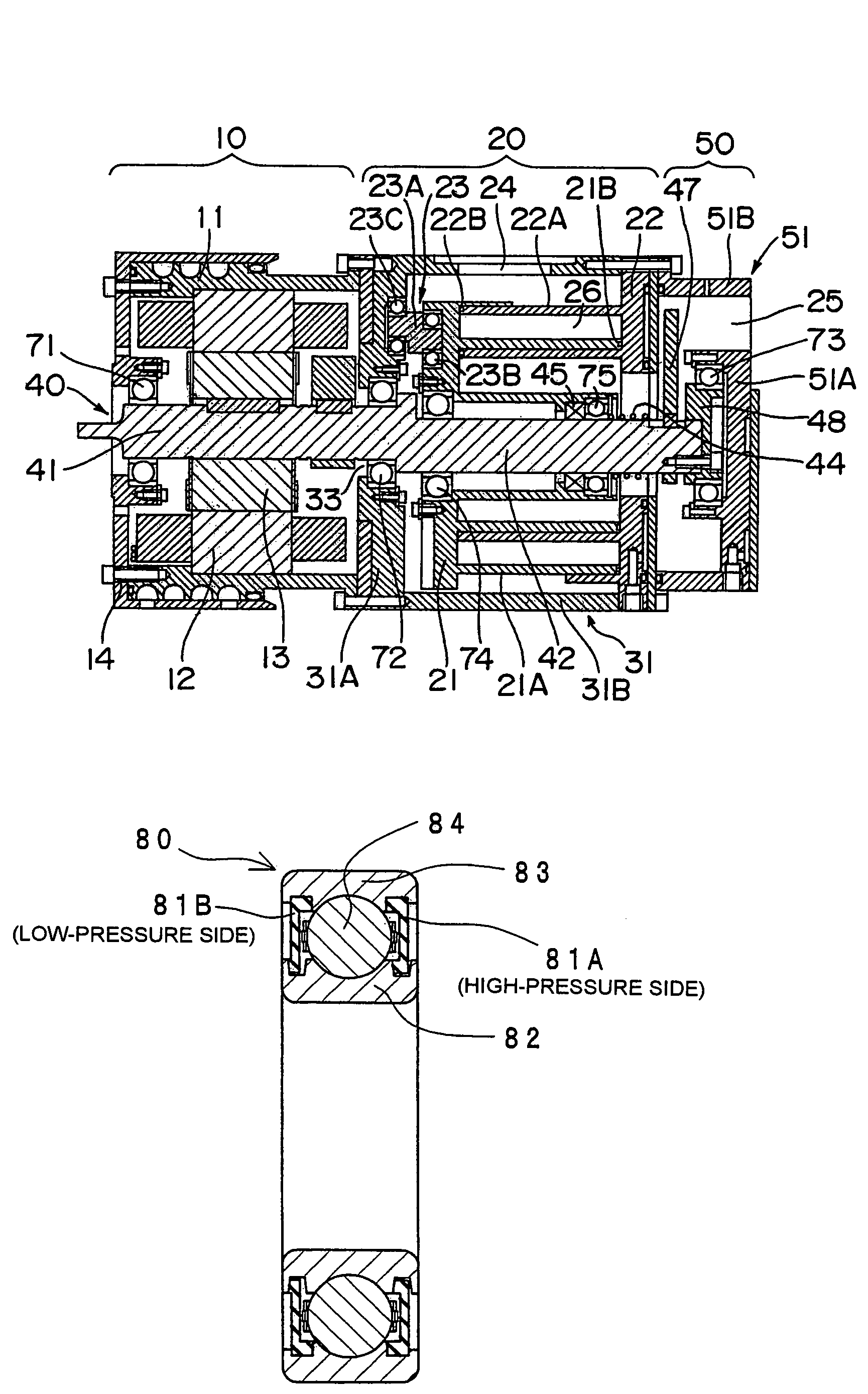
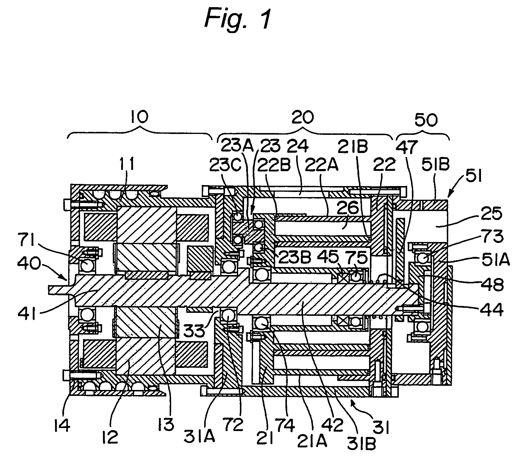
[0023]FIG. 1 is a sectional view taken along a longitudinal axis of an air supply device according to the present invention, particularly depicting a general construction of the air supply device.

[0024]As shown in FIG. 1, the air supply device according to the present invention includes a drive section (motor section) 10, a compression mechanism section 20, and a discharge casing section 50.

[0025]The drive section 10 includes a cylindrical motor frame 11, a stator 12 secured to an inner surface of the motor frame 11, a rotor 13 secured to a motor shaft 41 to rotate within the stator 12, and a motor bearing plate 14 for closing one end of the motor frame 11. The motor bearing plate 14 includes a first bearing 71 secured thereto at a central portion thereof, which in turn rotatably supports one end of the motor shaft 41.

[0026]The compression mechanism section 20 includes an or...


PUM


Abstract

An air supply device includes a plurality of bearings for rotatably supporting a shaft, a plurality of bearings for rotatably supporting an orbital scroll, and a plurality of bearings for rotatably supporting each of a plurality of rotation constraint members that prevents rotation of the orbital scroll about its own axis, but allows the orbital scroll to orbit relative to a stationary scroll. A grease-filled bearing is used as each of the bearings. Each of the bearings for supporting the orbital scroll includes two sealing materials disposed on respective sides of a plurality of rolling elements, and each of the sealing materials has an inner end held in contact with an inner ring and an outer end held in contact with an outer ring.

Description

TECHNICAL FIELD[0001]The present invention relates to an air supply device that is used as, for example, a supercharger for an engine or an air compressor for a fuel cell.BACKGROUND ART[0002]In fluid machinery, sliding portions are generally lubricated with oil in order to prevent seizing or abnormal wear or abrasion. Accordingly, a fluid discharged from the fluid machinery is somewhat mixed with the oil, and it is extremely difficult to remove the oil from the fluid. In view of this, use of bearings such as grease-filled ball bearings for the sliding portions has been suggested to perform lubrication only within the bearings for supply of a clean fluid (see, for example, Patent Document 1).[0003]Patent Document 1: Japanese Laid-Open Utility Model Publication No. 62-59788 (pages 9 and 10, FIG. 1)[0004]Use of grease-filled bearings is not limited, to fluid machinery, and they are generally used in various fields including the field of autommotive vehicles, the field of medical machin...

Claims


Application Information

Patent Timeline
Patent Type & Authority Patents(United States)
IPC IPC(8): F01C1/02F03C2/00F04C23/00F16C33/78
CPCF16C33/78F04C23/008F04C18/0215F04C2240/50F16C2360/42
Inventor SAKUDA, ATSUSHISAWAI, KIYOSHINAKAMOTO, TATSUYA
Owner PANASONIC CORP
Why Eureka
Try Eureka