
Diamagnetic current response transducer for sensing pressure gradient in a fluid medium

a transducer and diamagnetic current technology, applied in the field of seismic prospecting, can solve the problems of difficult to obtain a rigid connection between the housing of the motion sensor and water, the use of the motion sensor to measure the velocity of acoustic particles in a non-viscous fluid medium such as water is problematic, and the use of the motion sensor becomes difficul

Active Publication Date: 2007-11-13
EXXONMOBIL UPSTREAM RES CO
View PDF4 Cites 8 Cited by
  • Summary
  • Abstract
  • Description
  • Claims
  • Application Information

AI Technical Summary

Benefits of technology

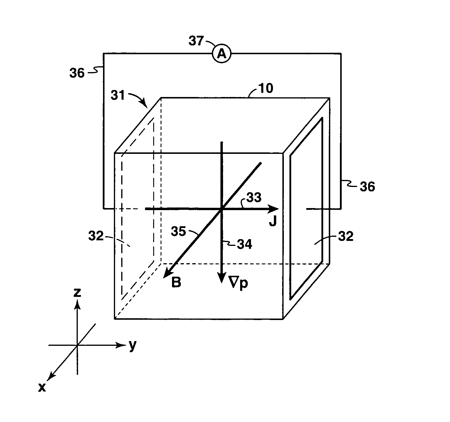
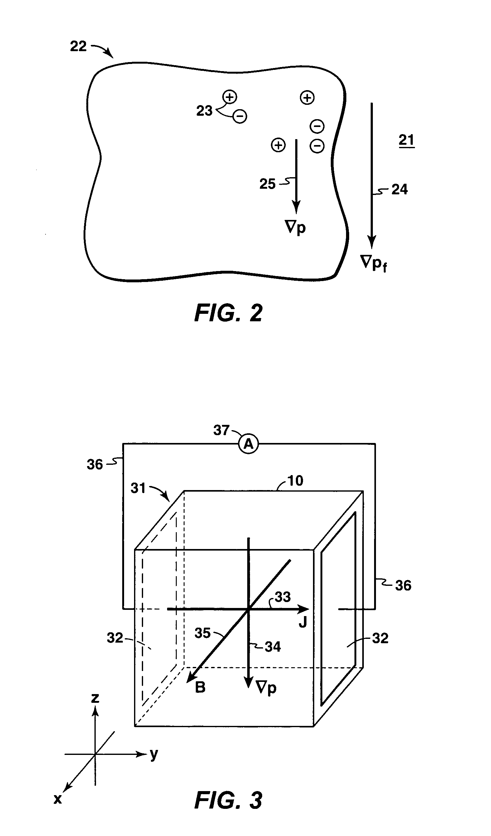
The invention is a sensor for measuring pressure gradients in a fluid volume. It consists of a transducer with mobile charged particles that exhibit diamagnetic drift under pressure gradients. The transducer is placed in contact with the fluid volume and an external magnetic field is applied. The diamagnetic current is collected with electrodes and measured using a current measuring device. The pressure gradient in the fluid volume is calculated from the measured current using an equation and known information on acoustic coupling properties between the fluid volume and the diamagnetic drift medium. The technical effect of this invention is to provide a reliable and accurate method for measuring pressure gradients in fluids.

Problems solved by technology

However, the use of motion sensors to measure acoustic particle velocity in a non-viscous fluid medium such as water is problematic.
First, it is difficult to obtain a rigid connection between the housing of a motion sensor and water, or other nonviscous fluid medium, so that the sensor housing will move as the medium moves.
Second, it is often the nature of water and other nonviscous fluid media to host a variety of flows and motions not related to acoustic waves propagating in the media.
Hence use of a motion sensor to measure acoustic particle velocity becomes difficult.
However, such methods are substantially limited in bandwidth and dynamic range compared to the individual hydrophone elements.
Under such circumstances, separation and relative orientation of two hydrophones may be variable, imposing an undesirable measurement system dynamic.

Method used


Image

  • Diamagnetic current response transducer for sensing pressure gradient in a fluid medium
  • Diamagnetic current response transducer for sensing pressure gradient in a fluid medium
  • Diamagnetic current response transducer for sensing pressure gradient in a fluid medium

Examples


Embodiment Construction

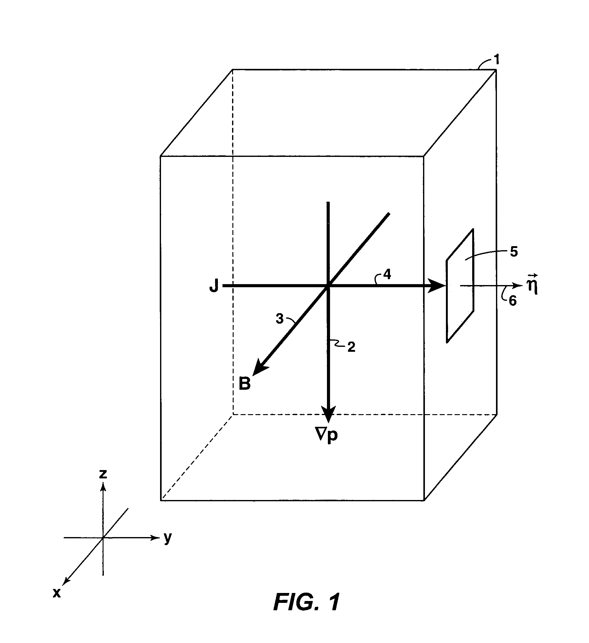
[0016]The proposed invention is a pressure gradient transducer (and method for using it) that employs the principle of diamagnetic current response of a system of mobile charged particles in a magnetic field to a pressure gradient orthogonal to the field. The invention provides a means to measure pressure gradient and, consequently, acoustic particle velocity of an acoustic wave in a fluid medium. The invention may be used for improved measurements of an acoustic wave near a low impedance boundary, or in combination with pressure measurements to determine acoustic intensity or direction of propagation, or to compensate effects derived from nearby boundary conditions; e.g., ghosting, multiple reflections, or to provide feedback for active acoustic boundary control.

[0017]The principle of diamagnetic drift is derived from the fluid description of systems of mobile charged particles. (See Francis F. Chen, Introduction to Plasma Physics and Controlled Fusion (New York: Plenum Press, 53-7...


PUM


Abstract

A pressure gradient sensor for seismic and other applications utilizing the principle of diamagnetic drift. The sensor comprises at least one transducer, each transducer made of or containing a medium having at least one species of mobile charged particles such as electrons or holes that exhibit diamagnetic drift under a pressure gradient. A magnet and a pair of electrodes are installed in each transducer. Diamagnetic drift current collected by the electrodes can be measured by an ammeter or similar device, and formulas and methods are disclosed to determine the pressure gradient from the measured current.

Description

[0001]This application claims the benefit of U.S. Provisional Patent Application No. 60 / 624,877 filed on Nov. 4, 2004.FIELD OF THE INVENTION[0002]This invention relates generally to the field of seismic prospecting in marine settings, and more particularly to receivers for seismic surveys. Specifically, the invention is a transducer for sensing pressure gradient in a fluid medium, and applicability of the invention is not limited to seismic surveying.BACKGROUND OF THE INVENTION[0003]A vast history exists on the topic of transducers. A brief description follows of existing devices for acquiring pressure gradient and acoustic particle velocity measurements, which may be categorized as follows; i) motion sensors, ii) multiple or arrayed pressure sensors, or iii) a broad category of many approaches including fiber optics, liquid crystals, and others. A more comprehensive discussion of these topics may be found in “Acoustic Particle Velocity Sensors: Design, Performance, and Applications...

Claims


Application Information

Patent Timeline
Patent Type & Authority Patents(United States)
IPC IPC(8): G01V1/18
CPCG01V1/186G01H11/02
Inventor MEIER, MARK A.
Owner EXXONMOBIL UPSTREAM RES CO
Learn More