
Surround surveillance apparatus for mobile body

a mobile body and surveillance technology, applied in the field of surround surveillance system, can solve the problems of increasing traffic accidents, affecting the safety of pedestrians, and many drivers and pedestrians not paying attention to their surroundings, so as to reduce the burden of drivers, improve safety, and quickly grasp the

Inactive Publication Date: 2007-11-13
SHARP KK
View PDF20 Cites 103 Cited by
  • Summary
  • Abstract
  • Description
  • Claims
  • Application Information

AI Technical Summary

Benefits of technology

[0028]In this way, a prepared image of a mobile body and a perspective image showing the mobile body and its surroundings which is obtained through an omniazimuth visual sensor are combined into an image to be displayed. From such a combined image, the operator of the mobile body can readily grasp a relative distance between the mobile body and objects around the vehicle. By using a previously captured image of the mobile body, the operator of the mobile body can readily grasp a relative distance between the mobile body and objects around the vehicle with more visual reality.
[0061]Thus, the invention described herein makes possible the advantages of (1) providing a surround surveillance apparatus for readily observing surroundings of a mobile body in order to reduce a driver's burden and improve the safety around the mobile body, and (2) providing a surround surveillance apparatus which can enable an operator of a mobile body to quickly grasp the conditions around the mobile body after the mobile body becomes movable.

Problems solved by technology

In recent years, an increase in traffic accidents has become a major social problem.
In particular, in a place where a plurality of roads meet (T-intersection, crossroad, or the like), various accidents may sometimes occur.
It is believed, in general, that such accidents are caused because a field of view for both drivers and pedestrians is limited in the crossroad area, and many of the drivers and pedestrians do not pay attention to their surroundings and cannot quickly recognize dangers.
However, the viewing range of a blind area which can be covered by a mirror is limited and, furthermore, a sufficient number of mirrors have not been installed.
However, even with such a surveillance system, the driver must check the safety of both sides of the vehicle manually using eyesight.
Furthermore, a single camera of this type has a limited field of vision such that the camera can detect obstacles and anticipate collisions only in one direction.
Such dew or frozen dew, or any other factor, may sometimes fog the window, causing difficulty for a driver to look outside from the inside of the vehicle.
When the driver starts to drive the vehicle under such circumstances, the driver of the vehicle cannot fully grasp the conditions around the vehicle unless the fog on the window of the glass is sufficiently wiped away or evaporated by warm air.
However, due to the shape and structure of the vehicle, there are blind spots / areas, i.e., areas that the driver cannot see directly behind and / or around the vehicle, and it is difficult for the driver to check the safety in such blind spots / areas.
As a result, such blind areas impose a considerable burden on the driver.
Such a manipulation is a considerable burden for the driver.
Furthermore, in the case where a window glass of a vehicle is fogged and it is difficult for a driver of the vehicle to see outside from the inside of the vehicle, the driver needs to increase the temperature inside the vehicle and wait until the fog on the window is cleared, or needs to wipe away the fog on the window so that the driver can check the safety around the vehicle manually using eyesight.

Method used


Image

  • Surround surveillance apparatus for mobile body
  • Surround surveillance apparatus for mobile body
  • Surround surveillance apparatus for mobile body

Examples


embodiment 1

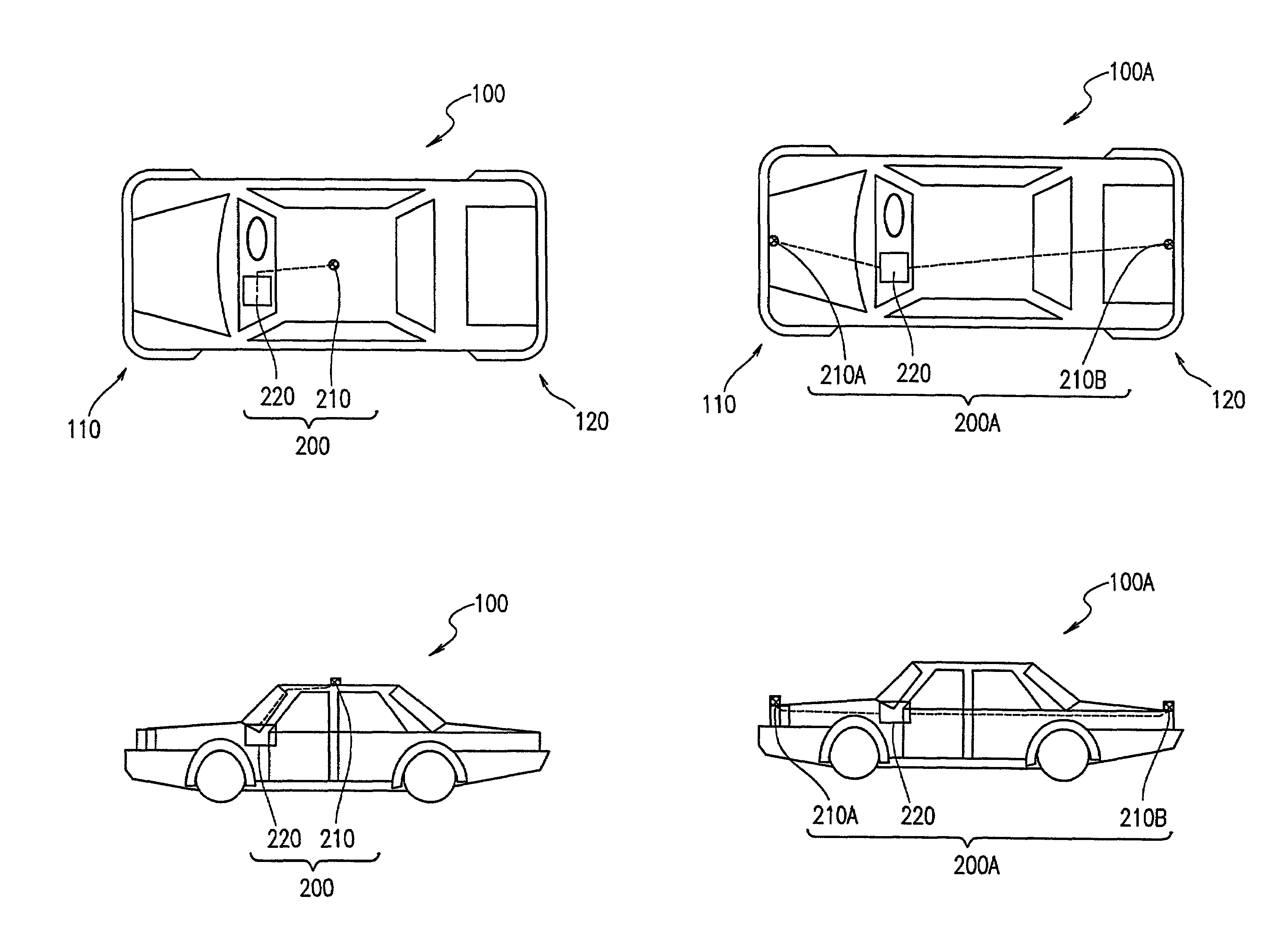
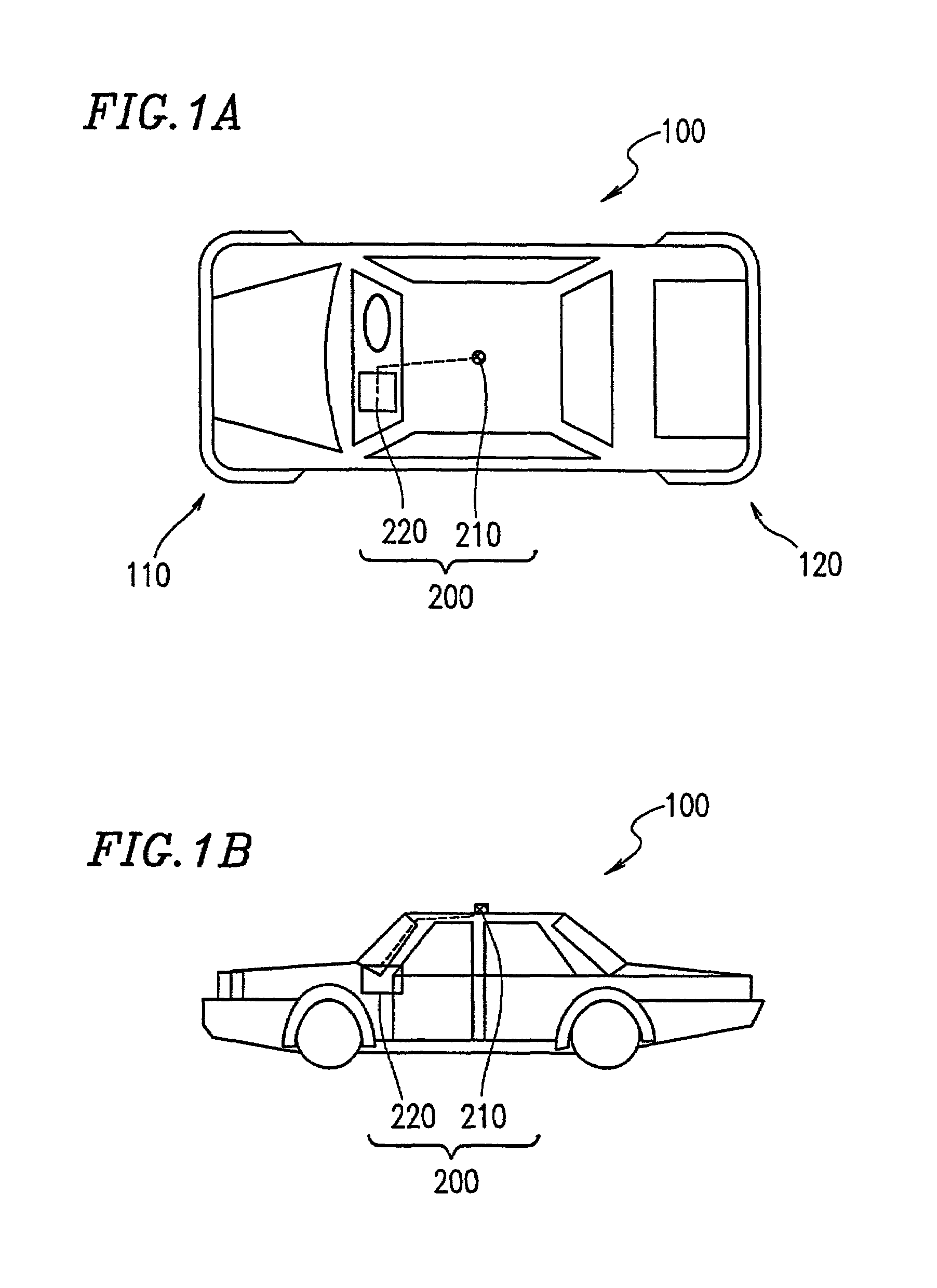
[0082]FIG. 1A is a plan view showing a structure of a mobile body 100 incorporating a surround surveillance apparatus 200 according to embodiment 1 of the present invention. FIG. 1B is a side view showing the mobile body 100 of FIG. 1A.

[0083]In embodiment 1, a vehicle is described as a specific example of the mobile body 100.

[0084]In embodiment 1, the vehicle 100 incorporates a surround surveillance apparatus 200 for a mobile body. As shown in FIGS. 1A and 1B, the surround surveillance apparatus 200 includes an omniazimuth visual sensor 210 and an arithmetic / control section 220. The omniazimuth visual sensor 210 is placed on a roof of the vehicle 100. The arithmetic / control section 220 is provided, for example, in a place near the driver's seat of the vehicle 100.

[0085]The omniazimuth visual sensor 210 shown in FIGS. 1A and 1B has an omniazimuth view filed with a 360° view field around itself in a generally horizontal direction.

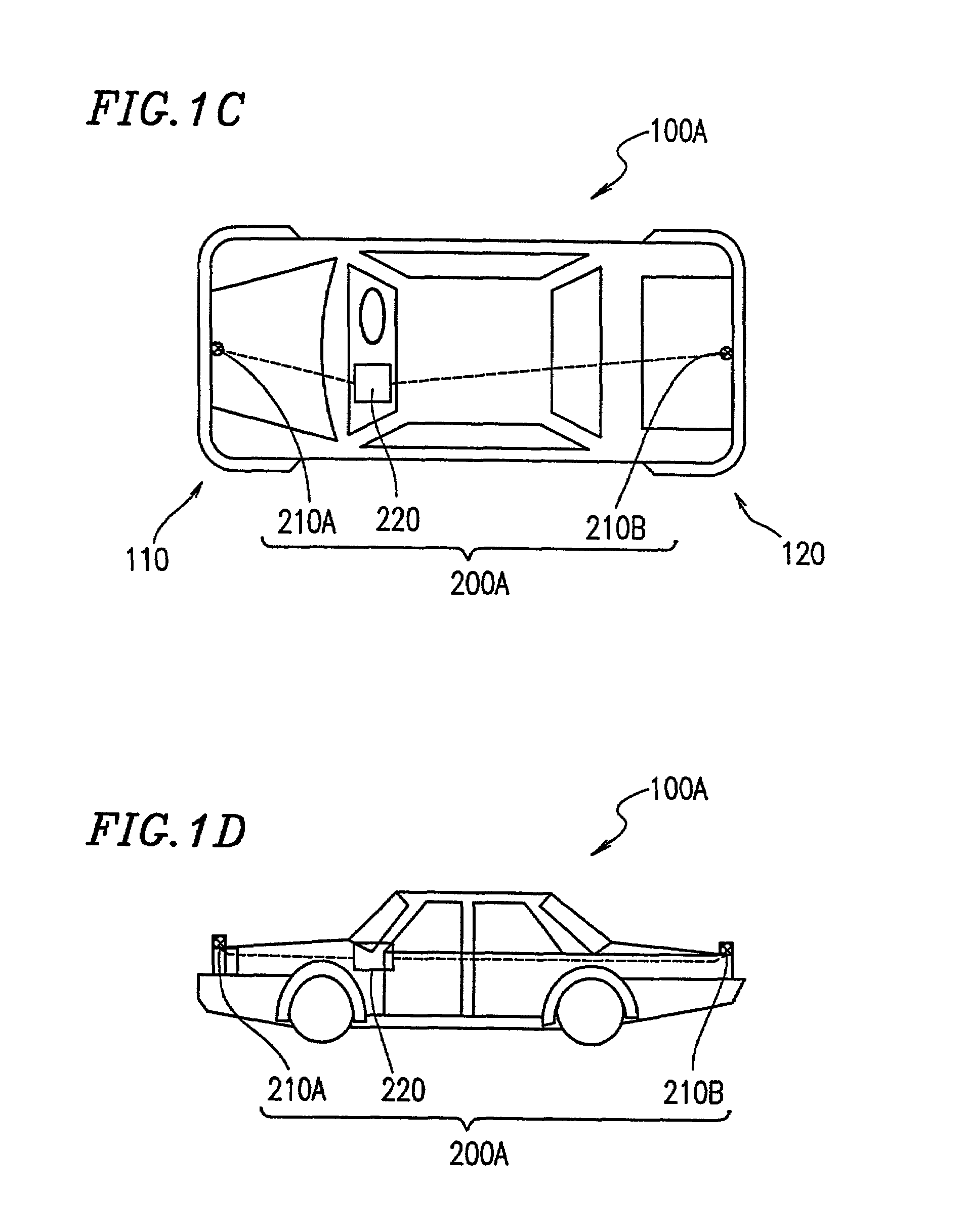
[0086]FIG. 1C is a plan view showing a structure of a m...

embodiment 2

[0137]FIG. 9A is a plan view showing a vehicle 900 which includes a surround surveillance apparatus 1000 for a mobile body according to embodiment 2 of the present invention. FIG. 9B is a side view of the vehicle 900.

[0138]Differences between the vehicle 900 of embodiment 2 and the vehicle 100A of embodiment 1 reside in that an omniazimuth visual sensor 100A is placed on the front right corner of the vehicle 900, and an omniazimuth visual sensor 1010B is placed on the rear left corner of the vehicle 900 diagonally to the sensor 1010A.

[0139]Each of the omniazimuth visual sensors 1010A and 1010B has an ominizimuth view field with a 360° view field around itself in a generally horizontal direction. However, one fourth of the view field (a left-hand half of the rear view field (90°)) of the omniazimuth visual sensor 1010A is blocked by the vehicle 900. That is, the effective view field of the omniazimuth visual sensor 1010A is limited to about 270° front view field. Similarly, one fourt...

embodiment 3

[0145]FIG. 12A is a plan view showing a structure of a vehicle 1200 incorporating a surround surveillance apparatus 1300 according to embodiment 3 of the present invention. FIG. 12B is a side view showing the vehicle of FIG. 12A.

[0146]The surround surveillance apparatus 1300 shown in FIGS. 12A and 12B is different from the surround surveillance apparatus 1000 in that a temperature measurement section 270 is provided at a position on the external surface of the vehicle 1200 which is optimum for measuring the environmental temperature (e.g., a frontal portion of the roof).

[0147]FIG. 13 is a block diagram showing a configuration of the surround surveillance apparatus 1300 according to embodiment 3. The surround surveillance apparatus 1300 is different from the surround surveillance apparatus 200 of FIG. 2 in that an arithmetic / control section 1320 of the apparatus 1300 includes the temperature measurement section 270.

[0148]In embodiment 3, as mentioned above, the temperature measuremen...


PUM


Abstract

A surround surveillance system mounted on a mobile body for surveying surroundings around the mobile body includes an omniazimuth visual system, the omniazimuth visual system includes at least one omniazimuth visual sensor including an optical system capable of obtaining an image with an omniazimuth view field area therearound and capable of central projection transformation of the image into an optical image, and an imaging section including an imaging lens for converting the optical image obtained by the optical system into image data, an image processor for transforming the image data into at least one of panoramic image data and perspective image data, a display section for displaying one of a panoramic image corresponding to the panoramic image data and a perspective image corresponding to the perspective image data and a display control section for controlling the display section.

Description

BACKGROUND OF THE INVENTION[0001]1. Field of the Invention[0002]The present invention relates to a surround surveillance system for surveying surroundings of a mobile body. Specifically, the present invention relates to a surround surveillance apparatus for surveying surroundings of a mobile body for human and cargo transportation, such as a car, a train, etc.[0003]2. Description of the Related Art[0004]In recent years, an increase in traffic accidents has become a major social problem. In particular, in a place where a plurality of roads meet (T-intersection, crossroad, or the like), various accidents may sometimes occur. For example, people rush out into the street in which cars are travelling, a car collides head-on or into the rear of another car, etc. It is believed, in general, that such accidents are caused because a field of view for both drivers and pedestrians is limited in the crossroad area, and many of the drivers and pedestrians do not pay attention to their surroundin...

Claims


Application Information

Patent Timeline
IPC IPC(8): H04N7/18G03B15/00B60R1/00B60R21/00G02B17/08G06T1/00G08G1/16
CPCB60R1/00H04N7/181G08G1/16B60R2300/102B60R2300/105B60R2300/30B60R2300/301B60R2300/607B60R2300/806B60R2300/8093B60R2300/602G08G1/168B60R1/27
Inventor KUMATA, KIYOSHIKAKO, NORITOSHI
Owner SHARP KK
Learn More