
Nitrification system and method

a nitrification system and nitrification technology, applied in the direction of filtration separation, multi-stage water/sewage treatment, separation process, etc., can solve the problems of low cell yield, low reliability of current nitrification technology in the conventional activated, and ammonia toxic to aquatic life forms at rather low concentrations, so as to reduce ammonia and enhance nitrification effect, increase the resistance of fluid flow, and reduce the effect of ammonia

Inactive Publication Date: 2007-11-13
GEYSER PUMP TECH
View PDF1 Cites 17 Cited by
  • Summary
  • Abstract
  • Description
  • Claims
  • Application Information

AI Technical Summary

Benefits of technology

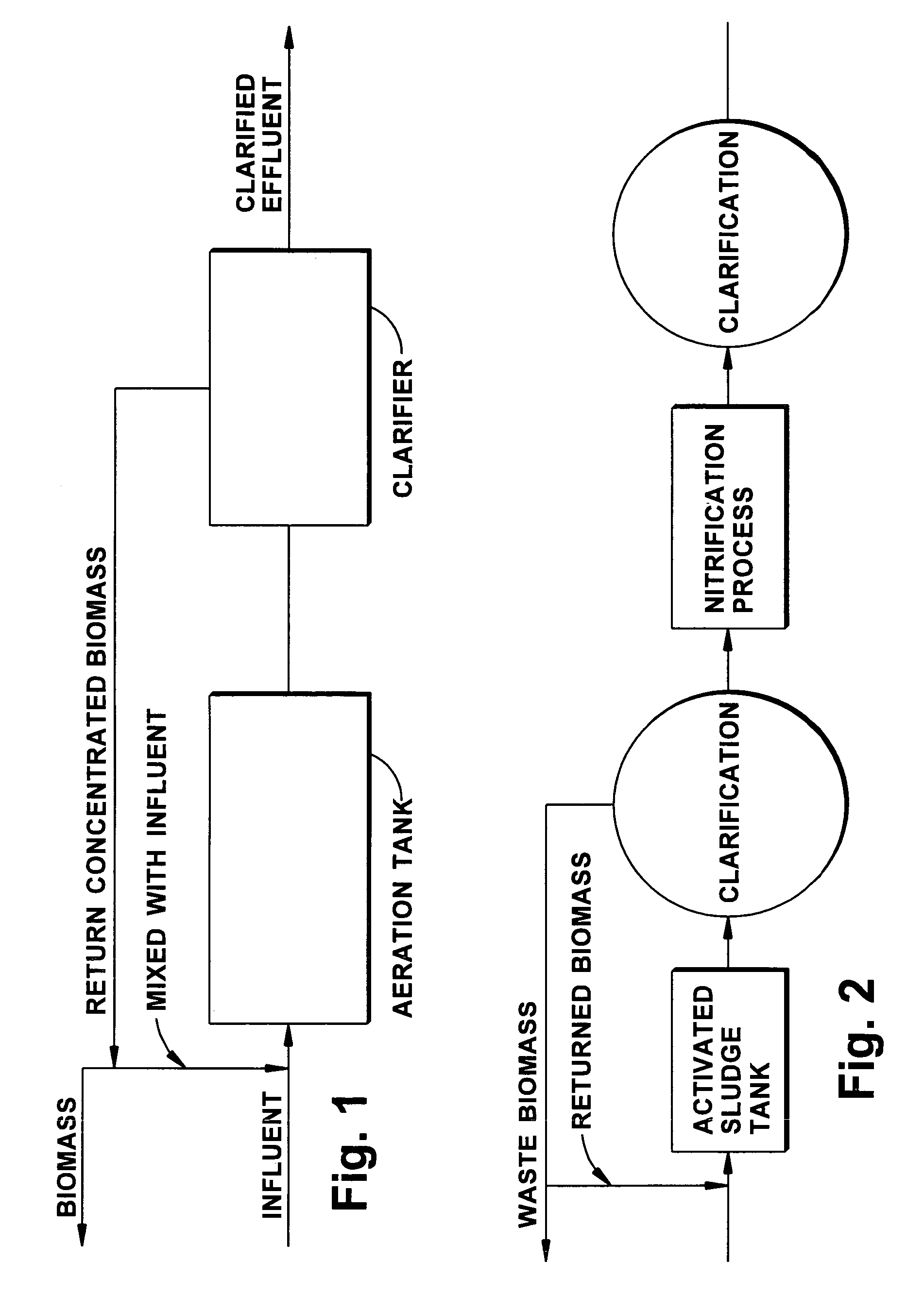
This configuration reduces ammonia concentrations effectively, improving effluent quality and reducing operational costs by maintaining adequate nitrifying bacteria and increasing dissolved oxygen levels, as demonstrated by a decrease in effluent ammonia from over 20 mg / l to less than 1 mg / l.

Problems solved by technology

Ammonia has been found to be toxic to forms of aquatic life at rather low concentrations.
In contrast, the autotrophs have a relatively low cell yield and relatively slow growth.
Many problems exist with the reliability of current nitrification technology in the conventional activated sludge process.
This causes a substantial impairment in the ability of the conventional activated sludge process to successfully achieve reliable nitrification in a one step system.
However these systems suffer from the same overgrowth and “wash-out” problems stated above.
Thus, in plants with a heavy carbonaceous load, nitrification cannot be undertaken effectively as an integral part of a normal activated sludge process.
Each of these separate nitrification processes is expensive to construct and operate.
In addition, the biomass produced is a weak, poor quality flow resulting in a poor quality effluent following clarification.
This type of design is subject to operational problems in cold weather, as the filters are subject to icing.
Additionally, natural sloughing of the filters results in poor quality effluent that requires additional treatment before discharge.
These disadvantages represent significant capital and operating costs.

Method used


Image

  • Nitrification system and method
  • Nitrification system and method
  • Nitrification system and method

Examples


Embodiment Construction

[0039]Conventional methods of reducing ammonia levels in sewage include biological treatment, chemical treatment using an ammonia stripping method, an ion exchange method, and / or chlorine dosing. Among these, biological treatment is most widely utilized due to its efficiency, economy, and easy maintenance.

[0040]The biological conversion of ammonia to nitrate, or nitrification, is described above, and as follows: ammonia is converted to nitrite (as typified by Nitrosomonas) by NH4+3 / 2O2→NO2−+H2O→2H+ and then nitrite to nitrate (by Nitrobacter) by NO2−+1 / 2O2→NO3−. Nitrifying bacteria (like Nitrosomonas and Nitrobacter) are sensitive organisms and extremely susceptible to a wide variety of inhibitors. From both laboratory studies and the operation of full-scale plants, the following factors have been determined to affect a nitrification process: 1) concentration of ammonia and nitrite; 2) BOD / TKN ratio; 3) dissolved oxygen concentration; 4) temperature; and 5) pH. A variety of organic ...


PUM

PropertyMeasurementUnit
concentrationsaaaaaaaaaa
temperatureaaaaaaaaaa
concentrationaaaaaaaaaa

Abstract

A system reduces ammonia within a fluid flow. The system includes an aeration vessel, a clarifier vessel, and a geyser pump. The aeration vessel nitrifies bacteria within the fluid flow. The aeration vessel has an intake flow rate. The clarifier vessel receives fluid from the aeration vessel. The geyser pump transfers activated sludge from the clarifier vessel to the aeration vessel. The geyser pump transfers activated sludge at a specific flow rate. The specific flow rate is less than 150% of the intake flow rate.

Description

RELATED APPLICATION[0001]This application claims priority from U.S. provisional patent application Ser. No. 60 / 707,859, filed on Aug. 12, 2005, the subject matter of which is incorporated herein by reference.TECHNICAL FIELD[0002]The present invention states that the field of the invention is nitrification system, and more particularly, a system for reducing ammonia in a fluid flow.DESCRIPTION OF THE PRIOR ART[0003]An activated sludge process is typically facilitated by an apparatus for enhancing nitrification. The conventional apparatus comprises the addition of a plurality of submerged, fixed support means to a conventional activated sludge system. These support means act as supports for autotrophic nitrifying bacteria and are utilized in the activated sludge process so that wastewater is substantially free of carbonaceous material by the time the wastewater reaches the support media. A circulation system is used to bring the wastewater into contact with the support media so that e...

Claims


Application Information

Patent Timeline
Patent Type & Authority Patents(United States)
IPC IPC(8): B01D3/04
CPCC02F3/12C02F3/223C02F2101/16Y02W10/10
Inventor KONDO, MASAO
Owner GEYSER PUMP TECH
Learn More