
Packaging machine and method for closing containers

a container and packaging machine technology, applied in the field of packaging machines and containers closing methods, can solve the problems of inconvenient change, inconvenient transportation, and inconvenient positioning of containers, and achieve the effect of convenient change and cost-saving

Inactive Publication Date: 2007-11-06
MULTIVAC SEPP HAGGENMULLER GMBH & CO KG
View PDF14 Cites 19 Cited by
  • Summary
  • Abstract
  • Description
  • Claims
  • Application Information

AI Technical Summary

Benefits of technology

[0011]It is a further advantage of the present invention that the packaging machine can easily be changed over to different container sizes and shapes and that in particular when only the height of containers is different no change over is necessary at all.
[0012]Furthermore, due to the employed linear motion of the plates into the closing device and out of the closing device, respectively, the packaging machine according to the invention can be realised significantly more cost-efficient than packaging machines using rotary motions. For this reason, the packaging machine can be formed in a space-saving manner in the direction perpendicular to the main transport path.

Problems solved by technology

It is disadvantageous that the positioning of the containers takes place in an imprecise way and takes a lot of time since the acceleration must remain low and the drivers must return from the region of the sealing station.
However, the positioning is imprecise and the transport takes a lot of time since a supply and a removal can only take place when the sealing station is opened and during this time no operation for evacuating, introduction of gas and sealing of the containers is possible.
Not until this is finished, the following containers can be transported into the sealing station and, therefore, the process in the sealing station takes a relatively long time since not only the time of sealing but additionally the transport time arises.
A relatively large space is needed in the horizontal direction perpendicular to the main transport path for the rotary motion which is in particular problematic when the packaging machine is used in small rooms.
Furthermore, relatively long trajectories have to be covered between the two positions of the receiving plates in the rotary motion and accelerations having rotary components as well as translatory components occur, thus limiting the possible transport speed.

Method used


Image

  • Packaging machine and method for closing containers
  • Packaging machine and method for closing containers
  • Packaging machine and method for closing containers

Examples


Embodiment Construction

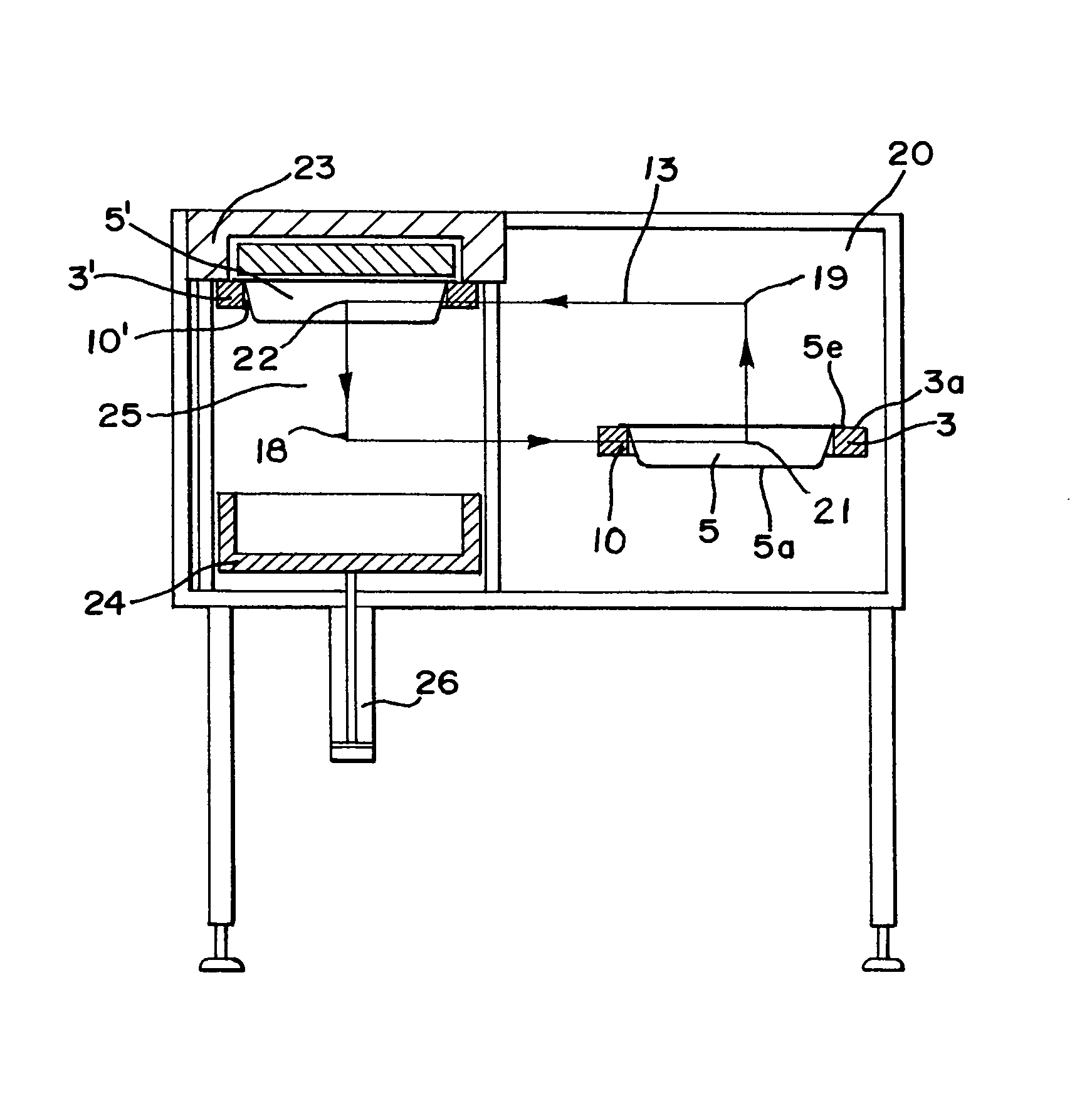
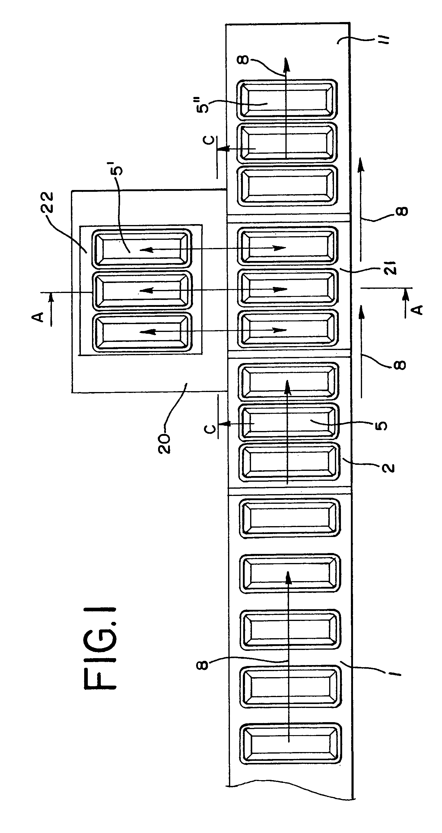
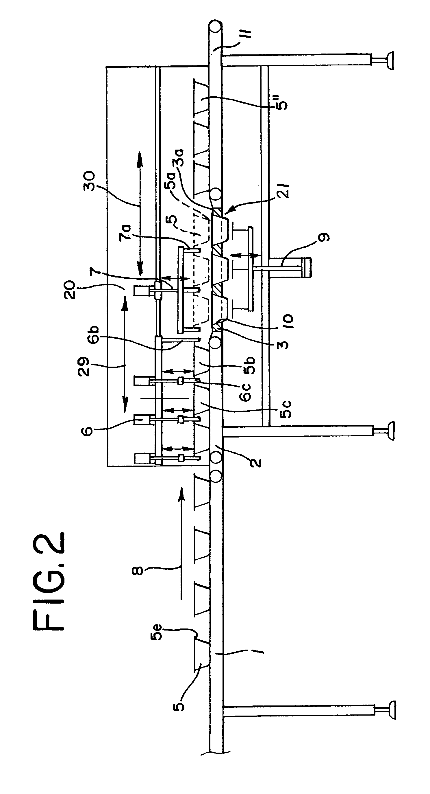
[0018]In the following, a first embodiment of the present invention is described with reference to FIGS. 1 to 4.

[0019]As shown in FIG. 2, the packaging machine of this embodiment includes a first supply conveyor belt 1 on which containers 5 to be closed are transported in direction to a closing station 20, a second supply conveyor belt 2 which is arranged in the input region of the closing station 20 and on which the containers 5 are grouped, as well as a removal conveyor belt 11 on which the containers 5″ are transported on after the processing in the closing station 20. The closing station 20 is formed such that a set of containers 5 can be processed simultaneously.

[0020]Via the first supply conveyor belt 1, the second supply conveyor belt 2 and the removal conveyor belt 11 the containers move along a main transport path in a main transport direction 8 which is indicated by an arrow in FIG. 2 and runs from the left to the right. The supply conveyor belts 1, 2 each run continuously...


PUM

PropertyMeasurementUnit
timeaaaaaaaaaa
accelerationaaaaaaaaaa
transport timeaaaaaaaaaa

Abstract

A packaging machine for closing containers (5) is provided having a supply device (1, 2) for supplying containers (5) to be closed; a removal device (11) for removing closed containers (5″); and a closing device (25) between the supply device (1, 2) and the removal device (11). The closing device (25) is arranged lateral of a main transport path (8) of the containers (5) from the supply device (2) to the removal device (11) and a device is provided which transports at least one container (5) to be closed into the closing device (25) by means of a linear motion while transporting at least one closed container (5″) out from the closing device (25).

Description

FIELD OF THE INVENTION[0001]The present invention relates to a packaging machine and to a method for closing containers.BACKGROUND OF THE INVENTION[0002]Packaging machines, so-called tray closing machines, are known in which products are packaged into pre-fabricated tray-shaped containers and closed with a film.[0003]From DE 690 03 503 a packaging machine is known in which the packaging containers are transported from a filling station onto a plate in a sealing station by means of circulating drivers. It is disadvantageous that the positioning of the containers takes place in an imprecise way and takes a lot of time since the acceleration must remain low and the drivers must return from the region of the sealing station.[0004]From EP 680 880 a machine is known in which the containers are directly transported from a supply unit into a closing device (sealing station) by pusher arms and, at the same time, the closed containers are removed from the closing device. Here as well, the con...

Claims


Application Information

Patent Timeline
Patent Type & Authority Patents(United States)
IPC IPC(8): B65B7/00B65B7/16B65B7/28B65B43/48
CPCB65B43/48B65B7/164
Inventor NATTERER, JOHANN
Owner MULTIVAC SEPP HAGGENMULLER GMBH & CO KG
Learn More