Ball motion measuring apparatus

a technology of motion measurement and ball, which is applied in the field of ball motion measurement apparatus, can solve the problems of difficult to predict the position of golf balls, reduce the angle of view of balls in images obtained by cameras having a great angle of view, and complicated work for often changing the position of cameras, etc., and achieve high precision

Inactive Publication Date: 2007-10-23
SUMITOMO RUBBER IND LTD
View PDF16 Cites 6 Cited by
  • Summary
  • Abstract
  • Description
  • Claims
  • Application Information

AI Technical Summary

Benefits of technology

[0012]In consideration of such problems, it is an object of the present invention to provide an apparatus for measuring the motion of a ball with high precision.
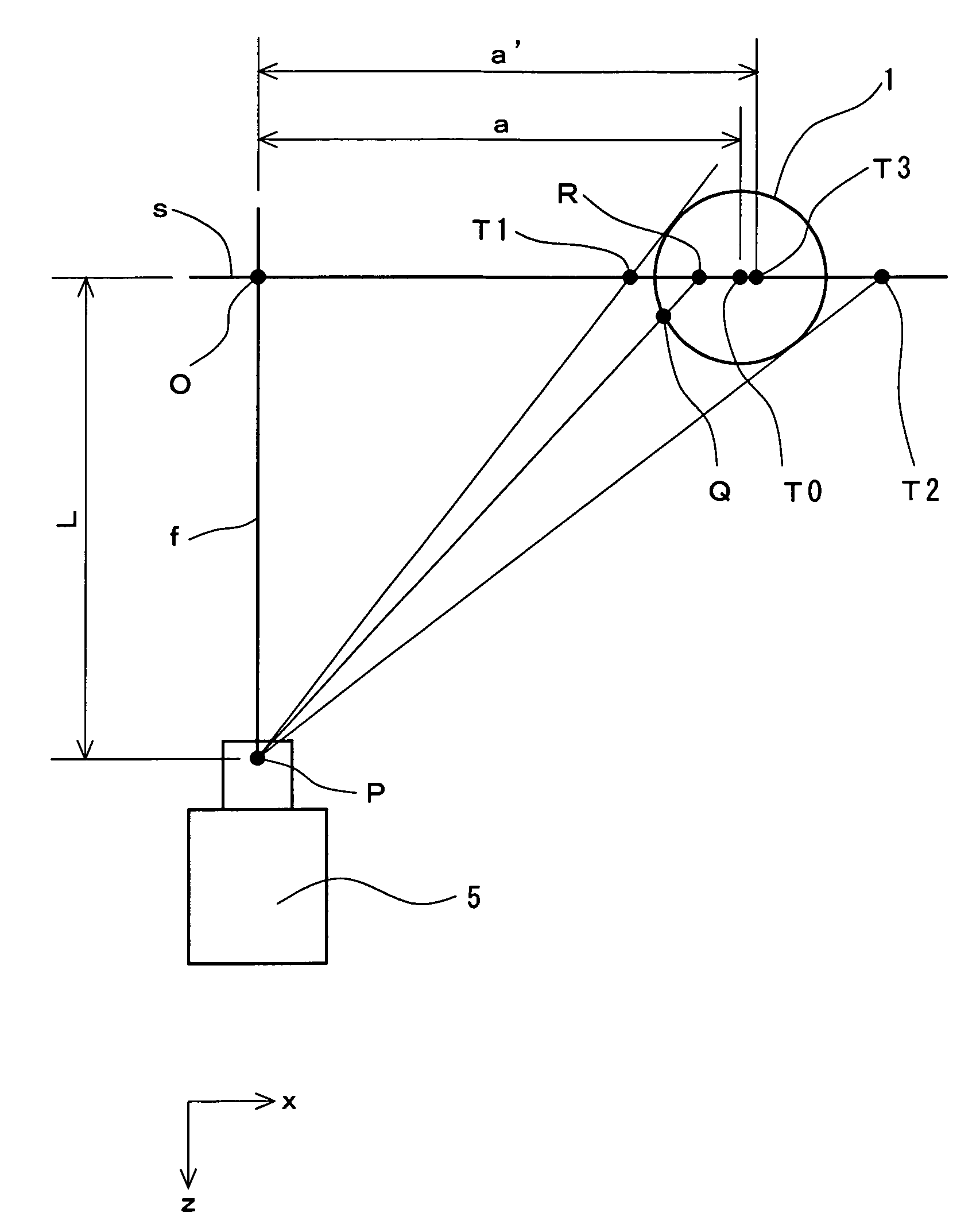
[0022]It is preferable that the coordinate error should be corrected based on a correction ratio determined by a distance from a center of the original image. Consequently, the precision in measurement can further be enhanced.

Problems solved by technology

Therefore, it is not easy to predict the position of the golf ball after the predetermined time passes since the hitting.
Even if the prediction can be carried out, a work for often changing the position of the camera is complicated.
However, a ball in an image obtained by the camera having a great angle of view is reduced.
Accordingly, in the case in which an operator specifies a predetermined point of the ball image through an input pen or the like to measure a spin rate, there is a problem in that precision in the pointing is deteriorated.
Moreover, the image obtained by the camera having a great angle of view has a considerable distortion in a peripheral portion (a portion having a great distance from the center of the image).
Therefore, true coordinates are considerably shifted from apparent coordinates on the image so that the precision in a measured value becomes insufficient in some cases.
Thus, the true coordinates are considerably shifted from apparent coordinates on the image so that precision in the measured value becomes insufficient.

Method used


Image

  • Ball motion measuring apparatus
  • Ball motion measuring apparatus
  • Ball motion measuring apparatus

Examples


experiment 1

Experiment Example A

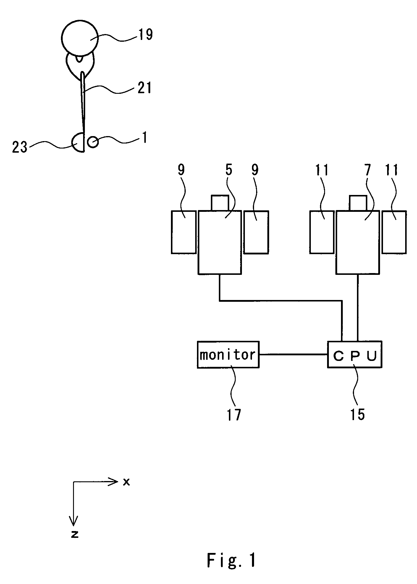
[0056]A CCD camera having a wide-angle lens was prepared for first and second cameras. In the CCD camera, a visual field range in a horizontal direction is 250 mm (a horizontal view angle of 45.24 degrees) when a distance between a focal point P and a reference plane is 300 mm. The positions of both cameras are regulated such that a ball image was photographed in almost the central part of an original image and a golf ball mounted on a tee was hit. The flying golf ball was photographed in a shifted timing by means of two cameras so that two original images were obtained. The original images were displayed on a monitor and a flight speed, a launch angle, a backspin rate and a sidespin rate of the golf ball were calculated through an operation for pointing a recognition mark by an operator. The pointing operation and the calculation were repeated ten times to obtain a variation (4×σ).

experiment example b

[0057]Original image data obtained in the experiment example A were subjected to a magnifying process having a double magnification ratio so that a magnified image was obtained. Based on the magnified image, the same pointing operation and calculation as those in the experiment example A were repeated ten times. Thus, a variation (4×σ) was obtained.

[0058]

TABLE 1Result of Experiment 1ExperimentExperimentExample AExample BType of lensWide angleWide angleMagnifyingNo× 2correction ratioDistortion correctionNoNoOblique correctionNoNoPosition of ball imagein original imageFirst cameraCenterCenterSecond cameraCenterCenterVariationFlight speed (m / s) 0.18 0.11Launch angle (deg.) 0.31 0.15Backspin rate (rpm)18088Sidespin rate (rpm)16884

[0059]In the Table 1, a measured value has a smaller variation in the experiment example B than that in the experiment example A. Consequently, it is apparent that precision in measurement can be enhanced by the magnifying process.

experiment 2

Experiment Example C

[0060]The same first and second cameras as those in the experiment example A were prepared. The position of the first camera was regulated such that a ball image can be photographed on the lower left part of an original image and the position of the second camera was regulated such that a ball image can be photographed on the upper right part of the original image. Then, a flying golf ball was photographed by means of the two cameras in a shifted timing. An original image thus obtained was subjected to a double magnifying process. Thus, two magnified images were obtained. The magnified images were displayed on a monitor so that a read value was obtained through an operation for pointing a recognition mark by an operator. A flight speed and a launch angle of the golf ball were calculated from the read value. The pointing operation and the calculation were repeated ten times. Thus, a mean value was obtained.


PUM


Abstract

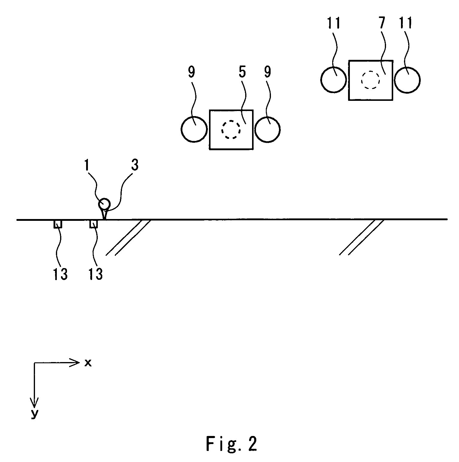
A ball motion measuring apparatus comprises a tee 3 for mounting a golf ball 1 thereon, a first camera 5, a second camera 7, a pair of first stroboscopes 9, a pair of second stroboscopes 11, a pair of optical sensors 13, a CPU 15 to be a calculating section, and a monitor 17 to be a display section. The first camera 5 and the second camera 7 are CCD cameras having a shutter function. Photographing is carried out by means of the first camera 5 after a predetermined time passes since the golf ball 1 is hit, and the photographing is carried out by means of the second camera 7 after a predetermined time further passes. A magnified image is formed by original image data thus obtained and a read value obtained by pointing the magnified image is subjected to distortion correction or oblique correction so that correction data are obtained. Based on the correction data, a flight speed, a spin rate or a launch angle of the golf ball 1 is calculated.

Description

BACKGROUND OF THE INVENTION[0001]1. Field of the Invention[0002]The present invention relates to a motion measuring apparatus for a ball such as a golf ball or a tennis ball. More particularly, the present invention relates to an apparatus for measuring the motion of a ball by utilizing image data obtained by a CCD camera.[0003]2. Description of the Related Art[0004]When a golf ball is hit with a golf club, it flies with a so-called backspin. The backspin is a rotation setting a horizontal direction orthogonal to a hitting direction (which will be hereinafter referred to as a “z direction”) to be an axis. A lift acts on the golf ball through the backspin, thereby increasing a flight distance of the golf ball. In some cases, the golf ball flies with a so-called sidespin. The sidespin is a rotation setting a vertical direction (which will be hereinafter referred to as a “y direction”) to be an axis. The golf ball turns left (a draw ball for a right-handed golf player) or turns right (...

Claims


Application Information

Patent Timeline
Patent Type & Authority Patents(United States)
IPC IPC(8): H04N7/18A63B69/36A63B69/00G01B11/03G01P3/36G01P3/38G01P3/40G01P3/68G01S3/784
CPCA63B24/0021A63B69/3658G01S3/784G01P3/38G01P3/40G01P3/68A63B2024/0034A63B2220/35A63B2243/0083A63B2102/02
Inventor YAMAMOTO, AKIOKAWAMATSU, HIDEAKI
Owner SUMITOMO RUBBER IND LTD
Why Eureka
Try Eureka