
Scanning microscope having a mirror for coupling-in a manipulating light beam

Active Publication Date: 2007-10-16
LEICA MICROSYSTEMS CMS GMBH
View PDF8 Cites 4 Cited by
  • Summary
  • Abstract
  • Description
  • Claims
  • Application Information

AI Technical Summary

Benefits of technology

[0008]It is an object of the present invention to provide a scanning microscope that, with flexibility and in simple fashion, makes possible manipulation of the sample using a rapidly movable manipulating light beam.
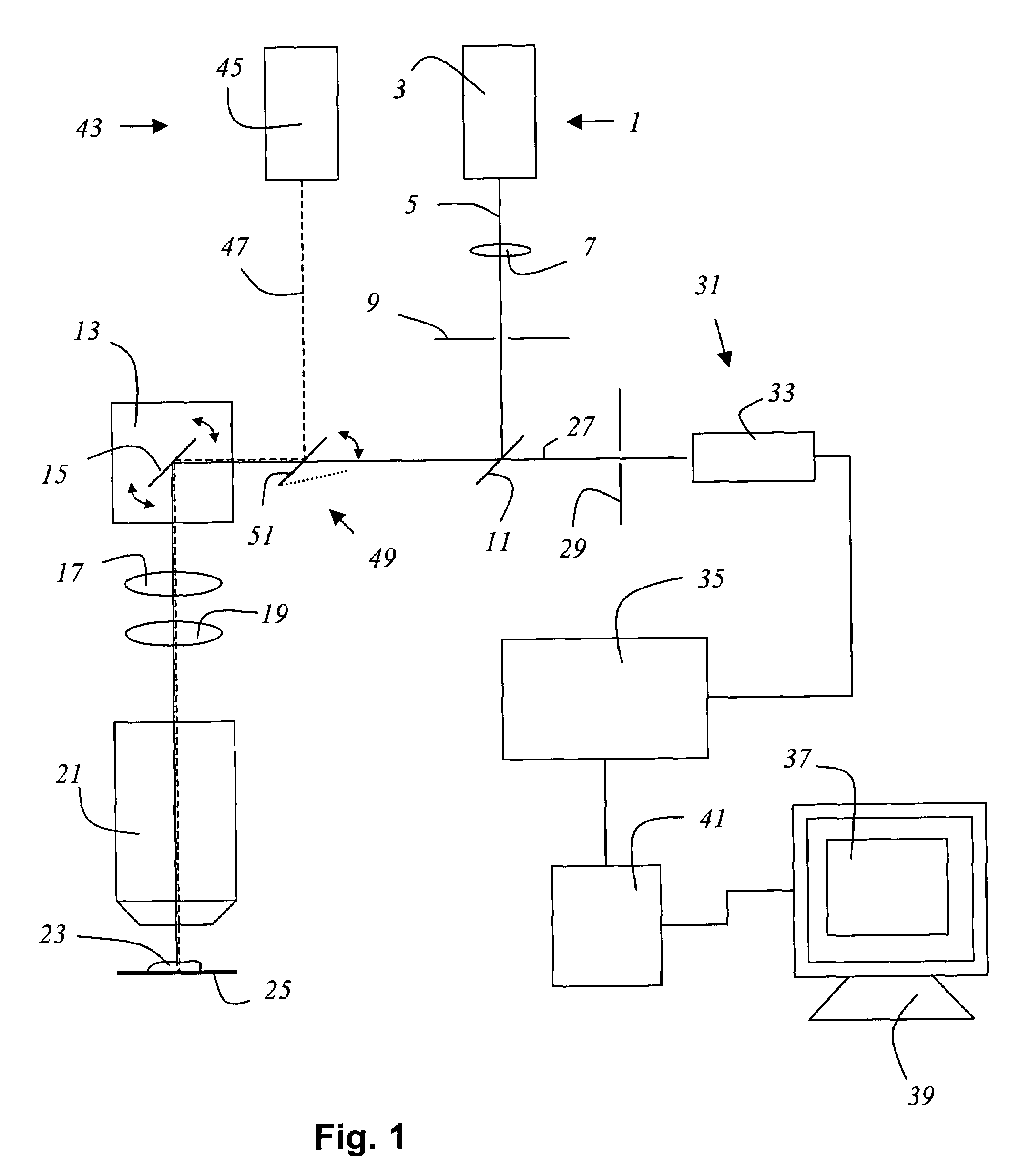
[0010]The invention has the advantage of making possible manipulation of the sample in simple fashion without influencing the alignment of the illumination beam path of the scanning microscope. Since the manipulating light beam is guided over or through the sample by the same beam deflection device as the illuminating light beam, the scanning microscope according to the present invention can be manufactured in particularly simple and economical fashion, a further beam deflection device being entirely superfluous.
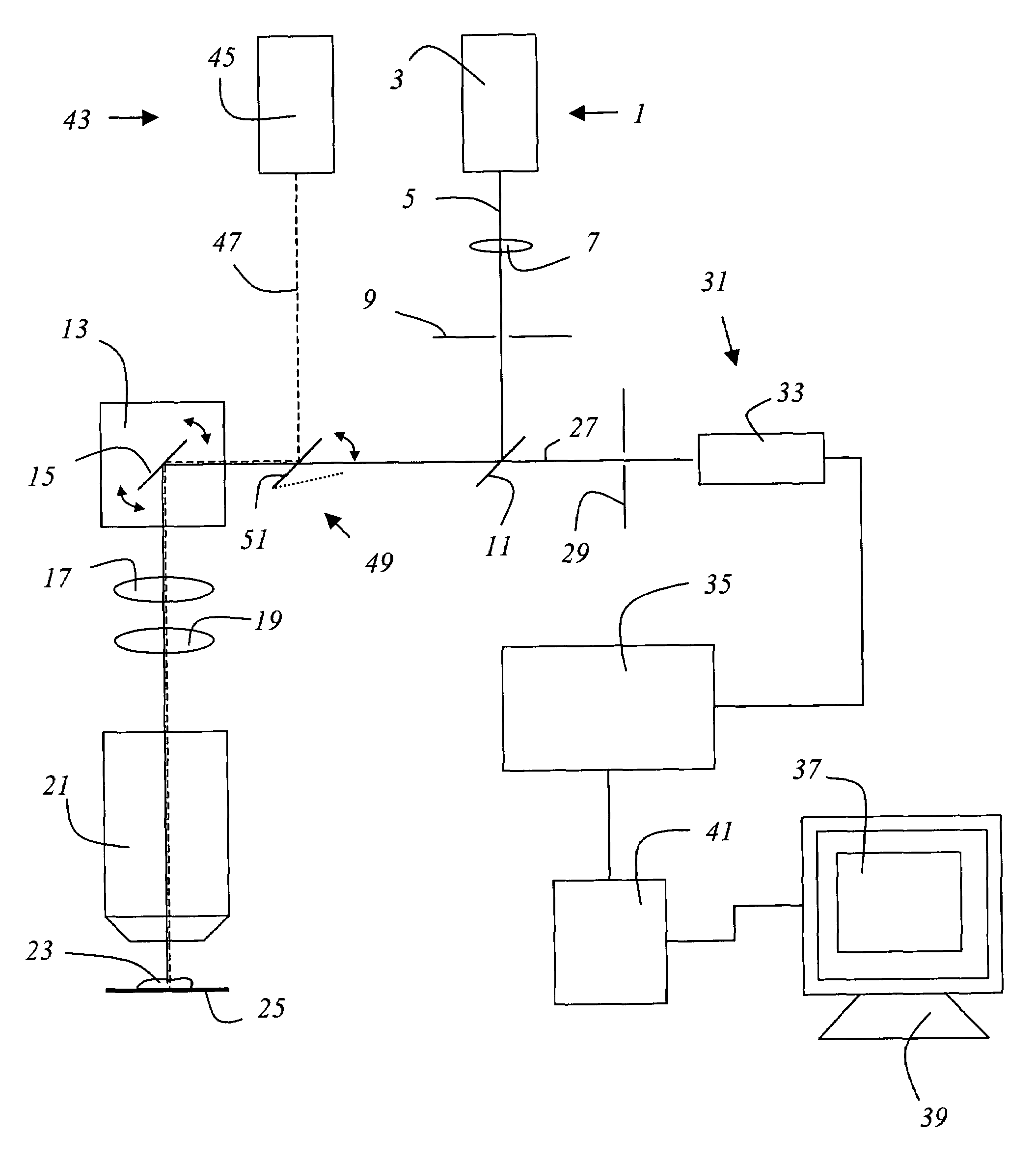
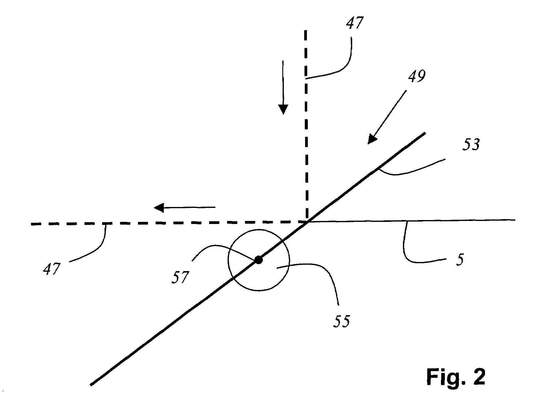
[0013]A preferred embodiment provides that the mirror introduced into the illumination beam path automatically interrupts the illuminating light beam in that position. A great advantage of this embodiment is that during manipulation of the sample—i.e. if light at a high power level (e.g. 488 nm, 200 mW) is inputted into the beam paths of the scanning microscope by way of the manipulating light beam—the detectors, which e.g. can be sensitive photomultipliers, are covered by the mirror and consequently protected, since they cannot be impinged upon or dazzled by residual light of the manipulating light beam, which would result e.g. in a long photomultiplier dead time and thereby prevent rapid measurement. In this embodiment, the mirror for the illuminating light beam is opaque and can preferably have a metal coating.
[0017]In the embodiment in which the mirror interrupts the illuminating light beam, the beam deflection device can guide the manipulating beam over the sample on any arbitrary scanning track, e.g. one defined by the user, that differs from the scanning track of the illuminating light beam.
[0018]In a preferred embodiment, the mirror is motor-driven, the motorized drive system preferably containing an actuating motor or a galvanometer. A galvanometer has the advantage that it makes possible rapid introduction and rapid withdrawal of the mirror, so that the manipulating light beam can be switched in and out even on a cycle of fractions of a second.

Problems solved by technology

This is disadvantageous for the user because displacement of the focus is necessarily associated with a change in the image area.
In addition, rapid movement of the focus is not possible.
The apparatus is, however, very costly and complex in terms of construction and operation.

Method used


Image

  • Scanning microscope having a mirror for coupling-in a manipulating light beam
  • Scanning microscope having a mirror for coupling-in a manipulating light beam
  • Scanning microscope having a mirror for coupling-in a manipulating light beam

Examples


Embodiment Construction

[0026]FIG. 1 schematically shows a confocal scanning microscope according to the present invention. The scanning microscope contains a light source 1 that is embodied as laser 3. Illuminating light beam 5 emitted from laser 3 is focused by optical system 7 onto an excitation pinhole 9 and, after passing through excitation pinhole 9, is reflected by a main beam splitter 11 to a beam deflection device 13 which contains a gimbal-mounted scanning mirror 15, and is guided by beam deflection device 13, through a scanning optical system 17, a tube optical system 19 and an objective 21, over or through sample 23. Sample 23 is positioned on a specimen stage 25 that, driven by a motor, is axially displaceable with respect to the optical axis of the illumination beam path. Detection light 27 proceeding from sample 23 travels back on the same light path through objective 21, tube optical system 19, scanning optical system 17, and beam deflection device 13 to main beam splitter 11, passes throug...


PUM


Abstract

A scanning microscope having a light source that emits an illuminating light beam, for illumination of a sample. The illuminating light beam extends along an illumination beam path and can be guided over and / or through the sample using a beam deflection device. A mirror which can be introduced in guided fashion into the illumination beam path directs a manipulating light beam via the beam deflection device onto the sample.

Description

CROSS REFERENCE TO RELATED APPLICATIONS[0001]This application claims priority to German patent application 102 47 249.1, the subject matter of which is hereby incorporated by reference herein. Furthermore, all references cited herein are hereby incorporated by reference herein.FIELD OF THE INVENTION[0002]The invention concerns a scanning microscope.BACKGROUND OF THE INVENTION[0003]In scanning microscopy, a sample is illuminated with a light beam in order to observe the reflected or fluorescent light emitted from the sample. The focus of an illuminating light beam is moved in a specimen plane by means of a controllable beam deflection device, generally by tilting two mirrors, the deflection axes usually being perpendicular to one another so that one mirror deflects in the X direction and the other in the Y direction. Tilting of the mirrors is brought about, for example, by means of galvanometer positioning elements. The power level of the detection light coming from the specimen is m...

Claims


Application Information

Patent Timeline
IPC IPC(8): G02B21/06G02B21/00
CPCG02B21/0032G02B21/002
Inventor KNEBEL, WERNER
Owner LEICA MICROSYSTEMS CMS GMBH
Learn More