
Apparatus and method for control of biopolymer translocation through a nanopore

a technology of biopolymer and nanopore, which is applied in the field of biopolymer control, can solve the problems of long time for effective, large amount of genomic dna in a patient, and inordinate amount of time and work

Active Publication Date: 2007-10-16
AGILENT TECH INC
View PDF10 Cites 50 Cited by
  • Summary
  • Abstract
  • Description
  • Claims
  • Application Information

AI Technical Summary

Benefits of technology

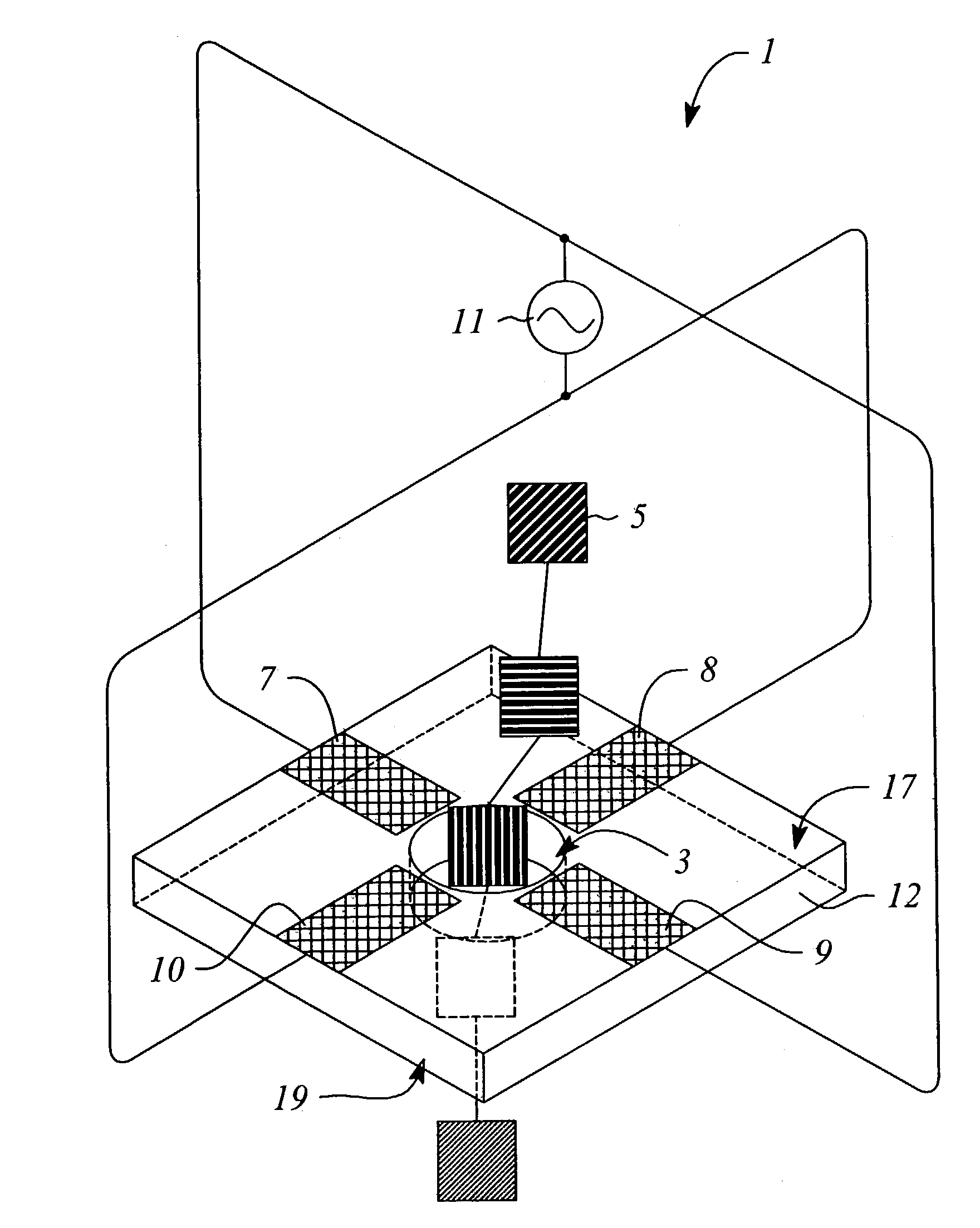
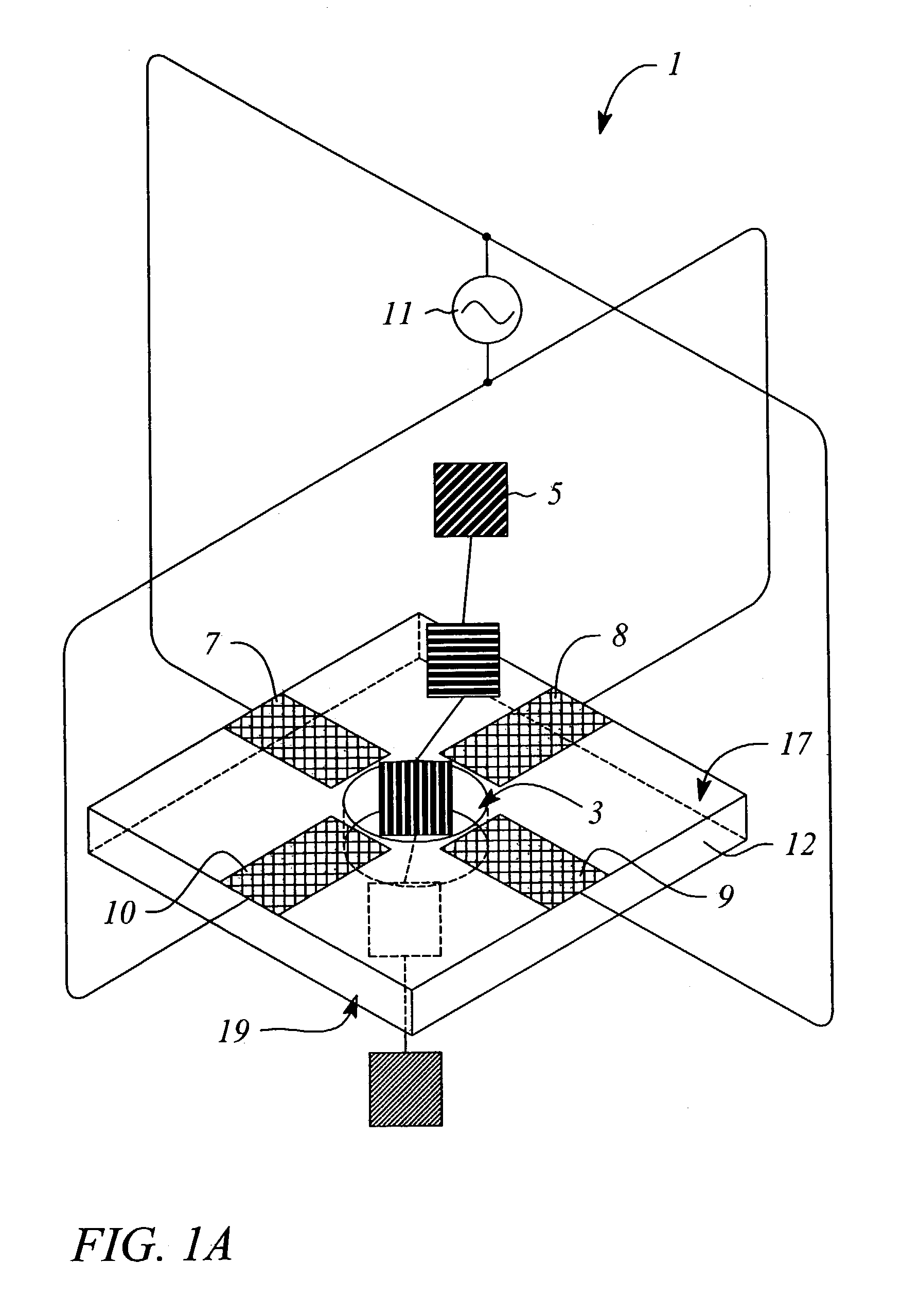
The invention provides a way to control how a biopolymer moves through a pore in a nanopore. This is done by using electric fields created by different sets of electrodes. The method can involve using one or more sets of electrodes or substrates with nanopores. The technical effect is the ability to better control the movement of biopolymers through nanopores, which can be useful in various applications such as DNA sequencing.

Problems solved by technology

A few major drawbacks of the micro array technique concern difficulty in manufacturing as well as the long time for effective hybridizations between probe and target (generally overnight to maintain high specificity).
In addition, the large amounts of genomic DNA in a patient would require an inordinate amount of time and work.
This blockage leads to a decrease in the ionic current flow of the buffer solution through the nanopore during the biopolymer translocation.
Both of the techniques described above have major implementation challenges for detecting biopolymer translocation, characterizing the length of a stand, and ultimately performing sequencing of the constituent bases of the biopolymer.
One of the primary difficulties is that the biopolymer is not constrained to pass through the center of the nanopore.
First, if the biopolymer is moved away from the center of the nanopore, interactions with the walls of the nanopore itself would cause additional drag, causing the speed of the translocation to decrease.
This variability would cause the measurement of the biopolymer length determined from the calibrated translocation time to be in error.
For this reason, it is expected that lateral displacement within the nanopore of the translocating biopolymer will cause significant variability in the magnitude of the measured ionic blockage current, making more difficult the job of differentiating the various bases by their blocking efficiencies, as described above.
As described for the first detection scheme, if the biopolymer is moved away from the center of the nanopore, interactions with the walls of the nanopore itself would cause additional drag, causing the speed of the translocation to decrease.
This variability would cause the measurement of the biopolymer length determined from the calibrated translocation time to be in error.
Secondly, it is well known that the tunneling current has an exponential dependence upon the height and width of the quantum mechanical potential barrier to the tunneling process.
For this reason, it is expected that lateral displacement within the nanopore of the translocating biopolymer will cause significant variability in the magnitude of the measured tunneling current, making more difficult the job of differentiating the various bases by their tunneling characteristics, as described above.
For all these reasons, variability of the lateral position of a biopolymer translocating a nanopore can cause significant problems, regardless of the detection scheme.
However, cited references or art are not admitted to be prior art to this application.

Method used


Image

  • Apparatus and method for control of biopolymer translocation through a nanopore
  • Apparatus and method for control of biopolymer translocation through a nanopore
  • Apparatus and method for control of biopolymer translocation through a nanopore

Examples


example 1

[0051]An example of the described device could be fabricated using techniques known to those skilled in the art. For instance, the nanopore can be made in a thin (500 nm) freestanding silicon nitride (SiN3) membrane supported on a silicon frame. Using a focused Ion Beam (FIB) machine, a single initial pore of roughly 500 nM diameter can be created in the membrane. Then, illumination of the pore region with a beam of 3 KeV Argon ion sputters material and slowly closes the hole to the desired dimension of roughly 2 nM in diameter (See Li et al., Nature, 412: 166–169, 2001). Metal electrodes are formed by patterning and evaporation, or other deposition means, to generate the quadrupole structure. Wire bonding to the metal electrodes allows connection to the RF voltage source. The RF voltage source has the modest requirements of several hundred microvolts at a frequency of 1.0 GHz.

example 2

[0052]A second example of the present invention would be similar to the first, however, and additional set of four electrodes are deposited on the opposing face of the substrate. The second set of electrodes are wired bonded in parallel to the RF voltage source, allowing coherent generation of the quadrupole fields over the length of the nanopore.


PUM

PropertyMeasurementUnit
sizeaaaaaaaaaa
sizeaaaaaaaaaa
frequencyaaaaaaaaaa

Abstract

The present invention provides an apparatus and method for controlling the movement of a biopolymer translocating a nanopore. The invention provides a first electrode, a second electrode adjacent to the first electrode, a third electrode adjacent to the second electrode and a fourth electrode adjacent to the third electrode. The first electrode is in electrical connection with the third electrode to define a first set of electrodes and the second electrode is in electrical connection with the fourth electrode to define a second set of electrodes. A DC voltage and radio frequency voltage is applied to the first set of electrodes while an opposite DC voltage and phase shifted radio frequency voltage is applied to the second set of electrodes to produce an electric field between the first set of electrodes and the second set of electrodes. The electric field is used to control the movement of a biopolymer translocating a nanopore. A method for controlling the movement of a biopolymer is also disclosed.

Description

TECHNICAL FIELD[0001]The invention relates generally to the field of biopolymers and more particularly to an apparatus and method for control of the movement of a biopolymer during translocation of a nanopore.BACKGROUND[0002]Manipulating matter at the nanometer (nm) scale is important for many electronic, chemical and biological advances (See Li et al., “Ion beam sculpting at nanometer length scales”, Nature, 412: 166–169, 2001). A number of sequencing techniques have been proposed at the micrometer and nanometer scale in response to the human genome project. These techniques have been largely developed to help characterize and understand expression of genes in vivo. A popular technique uses micro arrays and hybridization of cDNA to determine the presence or absence of a particular target gene. A target gene and probe are exposed in solution and bind if relative hybridization sequences match. Hybridization is indicative of the presence of the sequence or target gene. A dye may be em...

Claims


Application Information

Patent Timeline
Patent Type & Authority Patents(United States)
IPC IPC(8): G01N27/447G01N27/00G01N15/12
CPCB82Y5/00G01N33/48721B82Y30/00B82Y15/00
Inventor FLORY, CURT A.
Owner AGILENT TECH INC
Learn More