
Laminating product including adhesion layer and laminate product including protective film

a technology of adhesion layer and laminate product, which is applied in the field of adhesion layer, can solve problems such as peeling and cracks, and achieve the effects of reducing the likelihood of stress generation, preventing stress concentration, and reducing the moisture proof property

Inactive Publication Date: 2007-10-09
TOYOTA CENT RES & DEV LAB INC
View PDF22 Cites 18 Cited by
  • Summary
  • Abstract
  • Description
  • Claims
  • Application Information

AI Technical Summary

Benefits of technology

The present invention provides an organic / inorganic laminate structure with an adhesion layer between the inorganic and organic layers, which includes amorphous carbon nitride. This adhesion layer improves adhesion at the interface between the two materials and prevents peeling and cracks from occurring. The invention also provides an adhesion layer between an adhesive and a base member, which includes amorphous carbon nitride. This adhesion layer increases adhesion between the base member and the adhesive, regardless of the chemical bonding force between the two materials. The invention also provides a method for forming the adhesion layer using a vapor deposition method and a plasma enhanced chemical vapor deposition method. The invention further provides a laminate product with an adhesion layer between the inorganic and organic layers, which prevents peeling and cracks from occurring and increases adhesion between the layers. The organic member can be a thin film of an organic compound, a resin, or an adhesive. The inorganic member can be one or more of oxide, nitride, carbide, metal, or a combination of these materials.

Problems solved by technology

In addition, because most combinations of an inorganic member and an organic member provide a poor interface adhesion, there is a problem of peel-off and cracks.

Method used


Image

  • Laminating product including adhesion layer and laminate product including protective film
  • Laminating product including adhesion layer and laminate product including protective film
  • Laminating product including adhesion layer and laminate product including protective film

Examples


embodiment 1

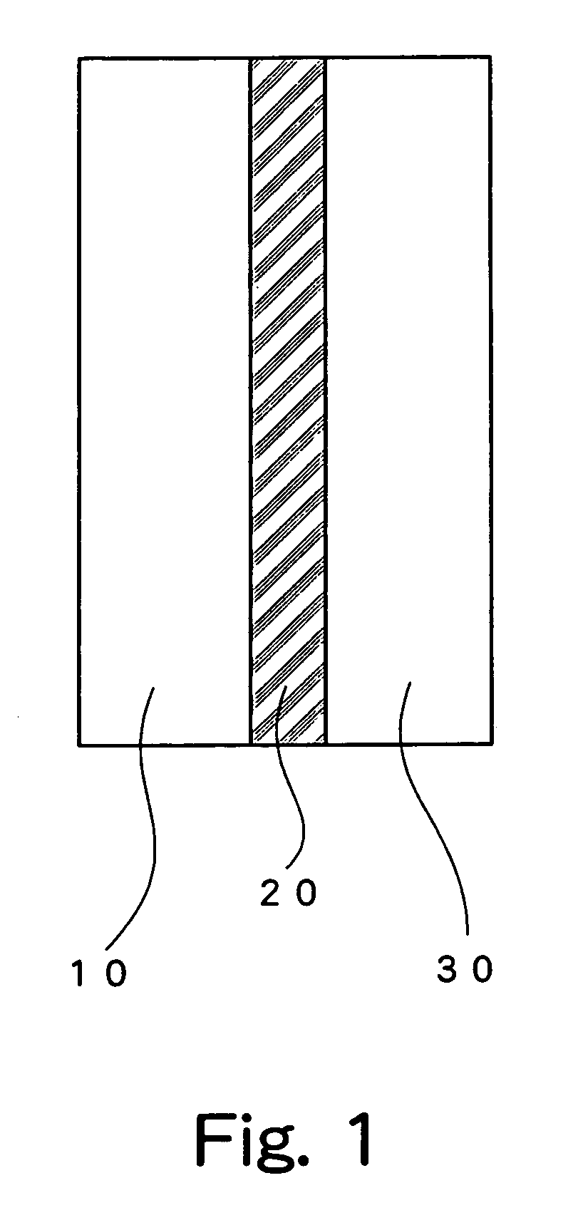
[0076]According to a first embodiment of the present invention, as shown in FIG. 1a laminate product comprises an adhesion layer 20 including amorphous carbon nitride (a-CNx:H where x is an arbitrary number) at an interface of a laminate structure formed by an inorganic member 10 and an organic member 30. As described above, an amorphous carbon nitride film includes carbon as its main component, and therefore has excellent wettability and high adhesion with respect to organic material. Also, because high Van der Waals force acts between the adhesion layer and the inorganic material due to the high density of the adhesion layer, high adhesion can also be obtained between the adhesion layer and the inorganic layer. Further, because the adhesion layer is a dense layer with excellent surface covering property, its adhesion force can further be improved.

[0077]The inorganic member and the organic member may have a base member in any state, such as a thin film, a thick film, or a substrate...

embodiment 2

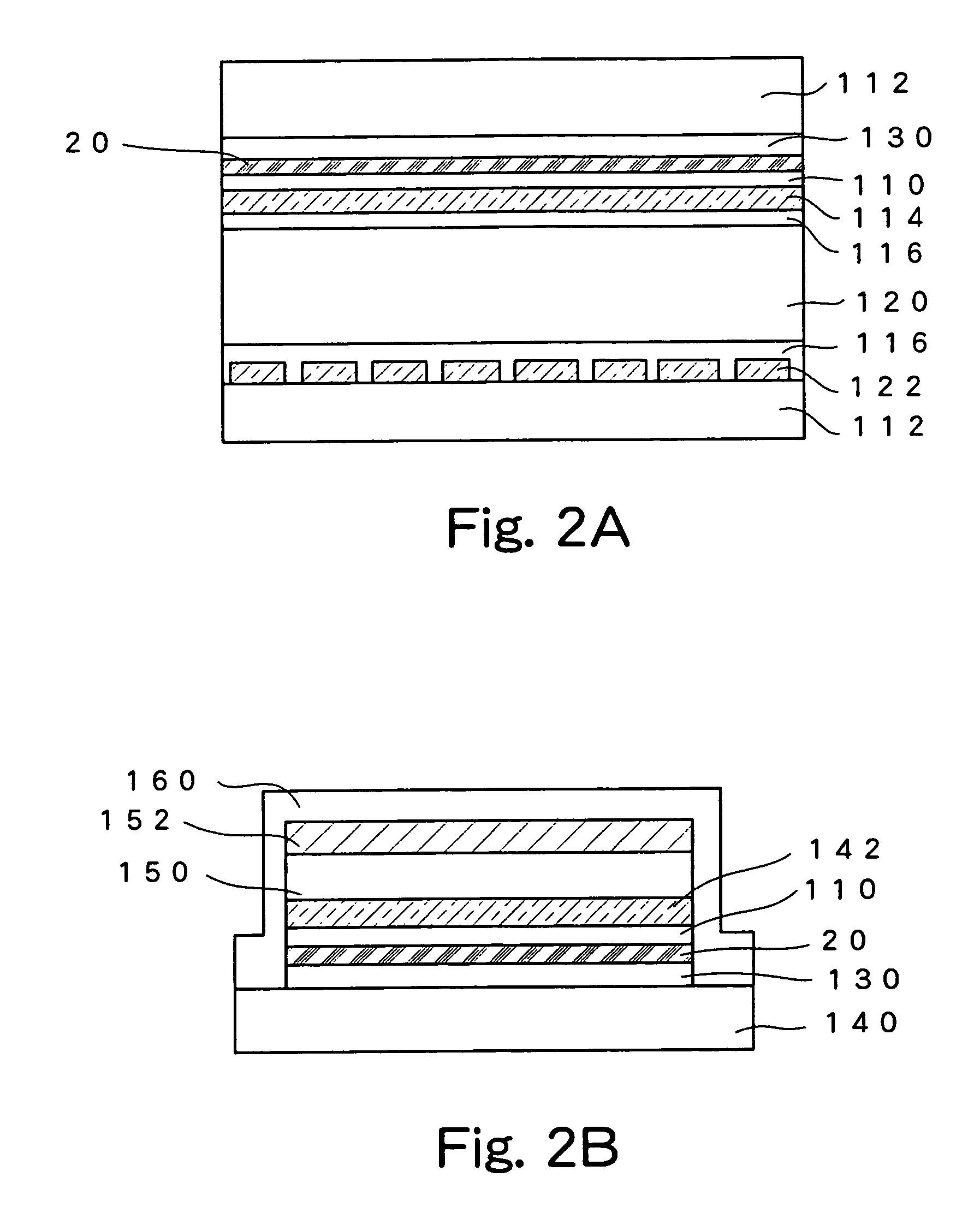
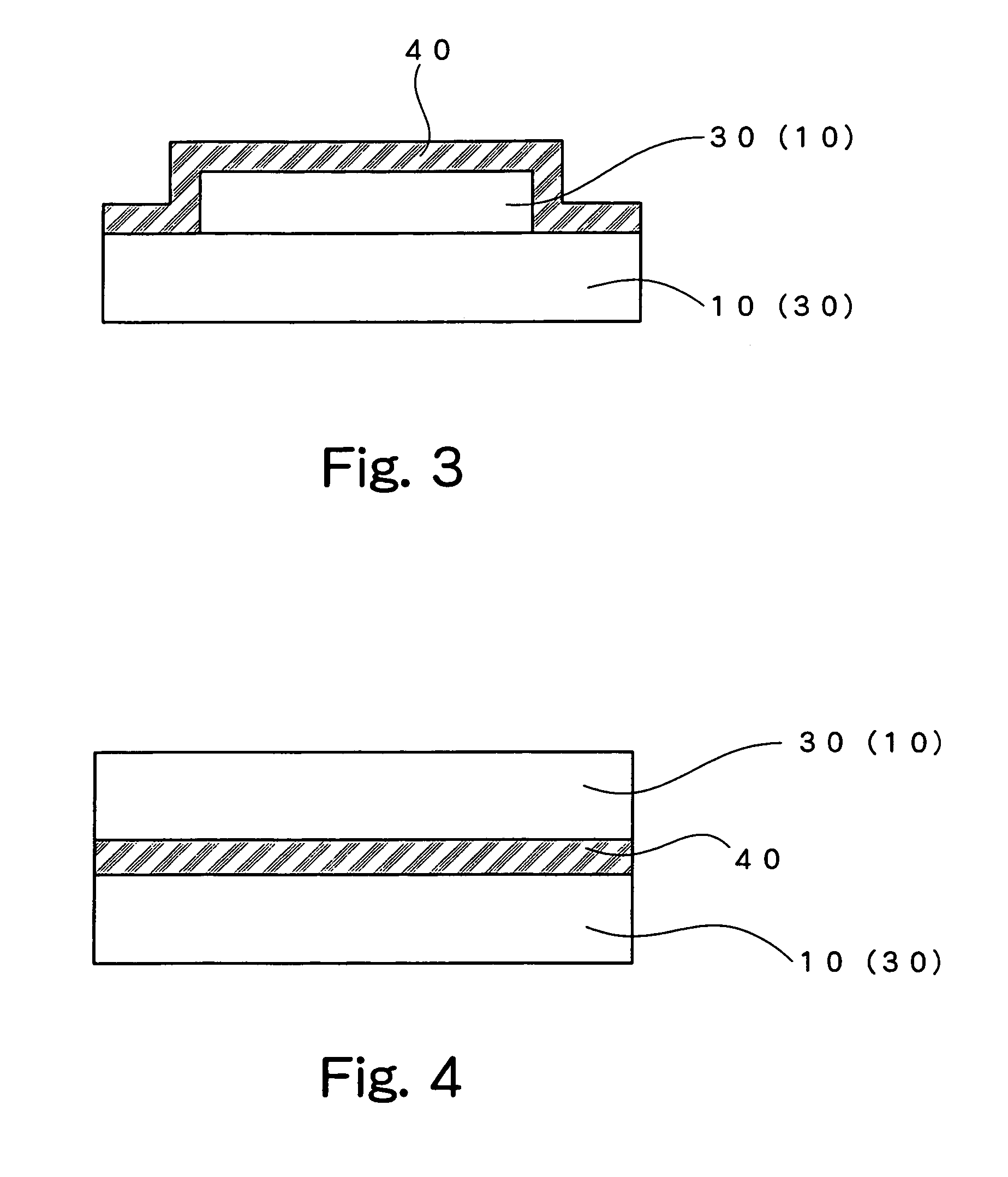
[0082]A second embodiment will be described. While amorphous carbon nitride (a-CNx:H) is used for an adhesion layer in the above first embodiment, in the second embodiment of the present invention, amorphous carbon nitride including hydrogen is used as a protective film. More specifically, a protective film covering a surface of a laminate base member in which inorganic members, organic members, or inorganic and organic member are lamimated, includes amorphous carbon nitride.

[0083]In any combination of films, namely, an organic member formed on an inorganic member, an inorganic member formed on an organic member, an inorganic member formed on an inorganic member, and an organic member formed on an organic member, when such a protective film is provided, the thin films of the laminate structure can be covered with high adhesion, and can therefore be protected from erosion by moisture, oxygen, and corrosive gas existing in the air and from mixture of impurities or the like.

[0084]Organ...

embodiment 3

[0110]A third embodiment of the present invention will be described. FIG. 9 shows a schematic sectional structure of an organic EL element of the third embodiment. The third embodiment differs from the second embodiment in that, in the third embodiment, in addition to the protective film 40 which covers the organic EL element on the second electrode 15 side, the protective film (buffer layer) 49 is further formed between the substrate 12 and the organic EL element (the first electrode 13 in this example). When a substrate which has superior flexibility and is yet more inexpensive than a glass substrate, for example, a plastic substrate, is used as the substrate 12 for forming the element, it is necessary to prevent intrusion of moisture and oxygen from the substrate side because the plastic substrate has lower shielding property than that of the glass substrate. By forming the protective film 49 between the substrate 12 and the organic EL element as shown in FIG. 9, the organic EL e...


PUM

PropertyMeasurementUnit
thicknessaaaaaaaaaa
total thicknessaaaaaaaaaa
thicknessaaaaaaaaaa

Abstract

In a laminate product formed by an organic member and / or an inorganic member, high strength adhesion between the organic member and the inorganic member is achieved by providing an adhesion layer which includes amorphous carbon nitride (a-CNx:H) particularly between the organic member and the inorganic member. Further, in order to protect a laminate product formed by an organic member and / or an inorganic member, for example, an organic electronic element including an organic compound layer, such as an organic electroluminescence element, a protective film including at least amorphous carbon nitride and a protective layer having a laminate structure formed by sandwiching a vapor deposition inorganic film between plasma polymerized films are used. Thus, a protective film which is optimum to an organic electronic element, having high bending stress resistance, high shielding effect against moisture and oxygen existing in the air, and excellent resistance to high temperature and high humidity can be provided.

Description

TECHNICAL FIELD[0001]The present invention relates to an adhesion layer for improving an adhesive property of a laminate product and a protective film for protecting a laminate product.BACKGROUND ART[0002]Laminate structures which is composed of a plurality of thin films formed on a base member are employed in a variety of technical fields. For example, a thin film is formed on a base member made of an inorganic or organic material, thereby forming an electronic device or protecting a surface of the base member as a protective film.[0003]In such a laminate structure, high adhesive strength of the thin film to the base member surface is often required so as to ensure reliability of the device, or for other reasons. Accordingly, in order to enhance the adhesion, various methods have been proposed, such as cleaning the base member surface or improving the surface quality, and providing an adhesion layer between the base member and the thin film.[0004]Cleaning of the base member surface...

Claims


Application Information

Patent Timeline
Patent Type & Authority Patents(United States)
IPC IPC(8): B32B9/00H01L51/50C23C16/34H01L51/52
CPCC23C16/347H01L51/5237Y10T428/26Y10T428/10Y10S428/917Y10T428/31504C09K2323/00H10K59/8731H10K50/8445
Inventor AKEDO, KUNIONODA, KOJIMIURA, ATSUSHIFUJIKAWA, HISAYOSHITAGA, YASUNORI
Owner TOYOTA CENT RES & DEV LAB INC
Learn More