
Cell-based switch fabric with distributed scheduling

a cell-based switch fabric and distributed scheduling technology, applied in the field of high-capacity switch fabric, can solve the problems of limiting the throughput of the switch, affecting the smooth operation of the switch, so as to achieve compact and efficient, low memory requirements

Inactive Publication Date: 2007-10-02
CALLAHAN CELLULAR L L C
View PDF45 Cites 83 Cited by
  • Summary
  • Abstract
  • Description
  • Claims
  • Application Information

AI Technical Summary

Benefits of technology

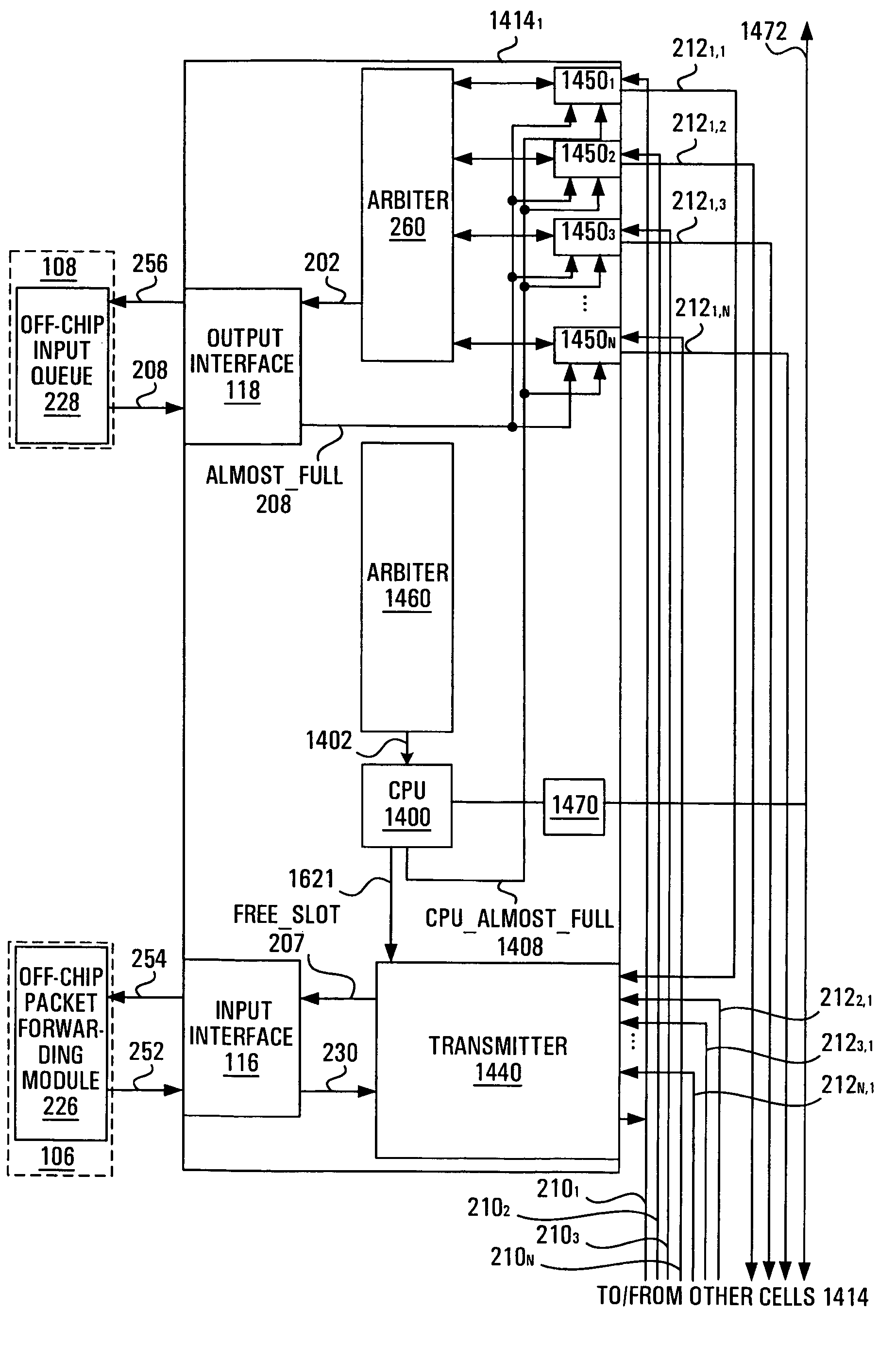
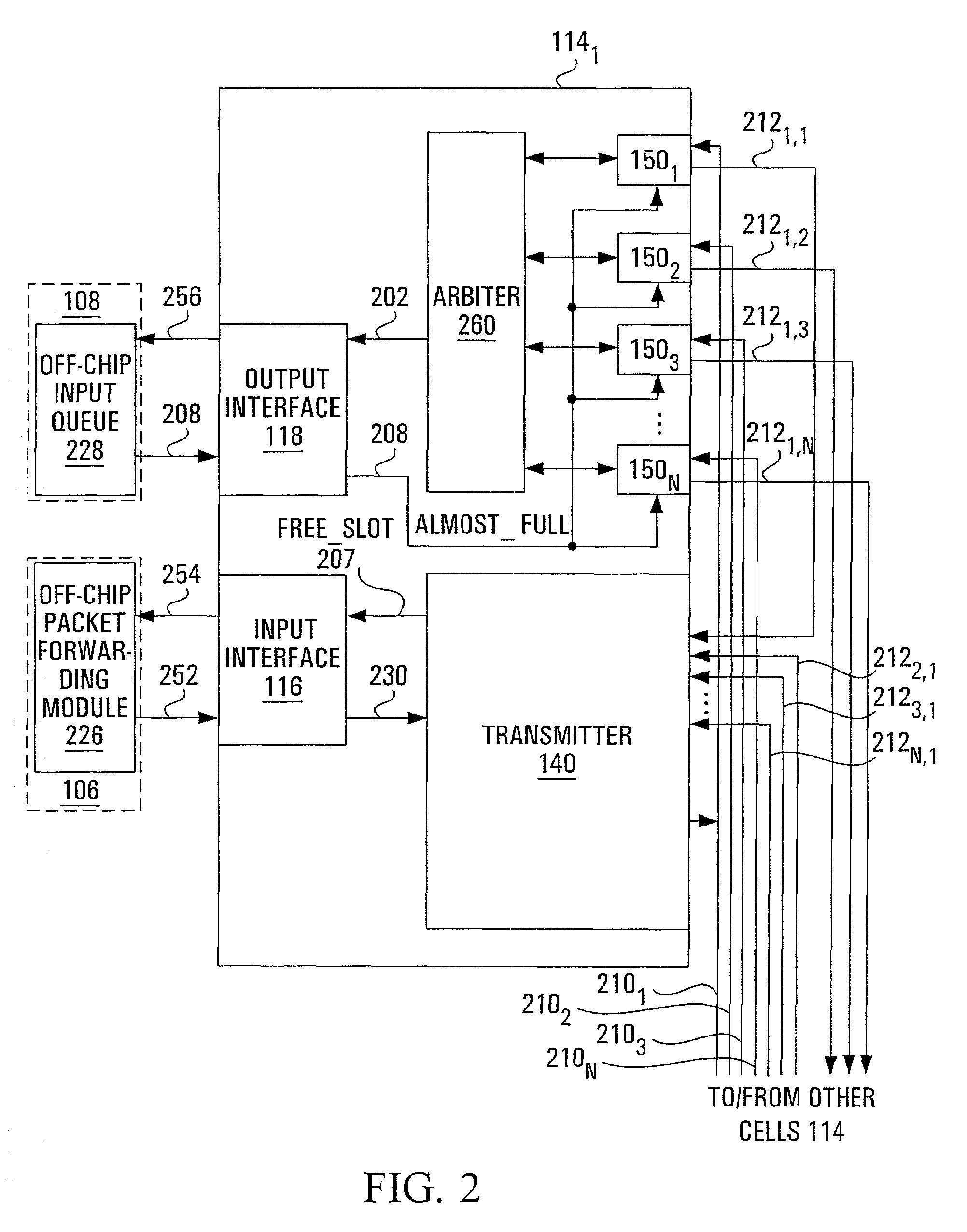
[0017]The present invention provides a compact and efficient switch fabric with distributed scheduling, arbitration and buffering, as well as a relatively low requirement for memory, allowing the switch fabric to be implemented on a single mass-producible semiconductor chip.

Problems solved by technology

However, packet switches face problems inherent to the random nature of packet traffic.
A first problematic situation may arise when two packets with different destination output ports arrive at the same input port of the switch.
Unfortunately, the centralized nature of the scheduling operation disadvantageously limits the throughput of the switch as the data rate increases, since the scheduler in the packet switch will usually be unable to keep up with the task of timely scheduling multiple packet streams at high data rates.
A second problematic situation, known as “contention”, arises when two or more packets from different input ports are destined for the same output port at the same time.
If an attempt is made to transmit both packets at the same time or within the duration of a packet interval, then either one or both packets will be lost or corrupted.
However, the centralized nature of arbitration again disadvantageously limits the throughput of the switch as the data rate increases, since the arbiter in the packet switch will not be able to keep up with a large number of packet streams at high data rates.
As the size and capacity of a switch increases, so does the complexity of the scheduling and arbitration.
This increase in complexity of the scheduling and arbitration entails an increase in latency, which consequently increases the memory requirement.
As a result, traditional approaches to scheduling and contention resolution have yielded packet switch designs that require large buffer sizes and complex, centralized scheduling and arbitration circuitry.
These properties make it impractical to lithograph a traditionally designed high-performance packet switch with a reasonable number of input and output ports onto a single semiconductor chip using available technology.
For this reason, traditional solutions have been implemented on multiple chips and therefore suffer from other problems such as high power consumption, high packaging costs, exposure to electromagnetic interference and significant inefficiencies and cost penalties related to mass production.
As the required switching capacity of packet switches increases to 1012 bits per second and beyond, traditional packet switches will be forced to further increase their memory size and complexity, with an associated exacerbation of the problems inherent to a multichip design.

Method used


Image

  • Cell-based switch fabric with distributed scheduling
  • Cell-based switch fabric with distributed scheduling
  • Cell-based switch fabric with distributed scheduling

Examples


Embodiment Construction

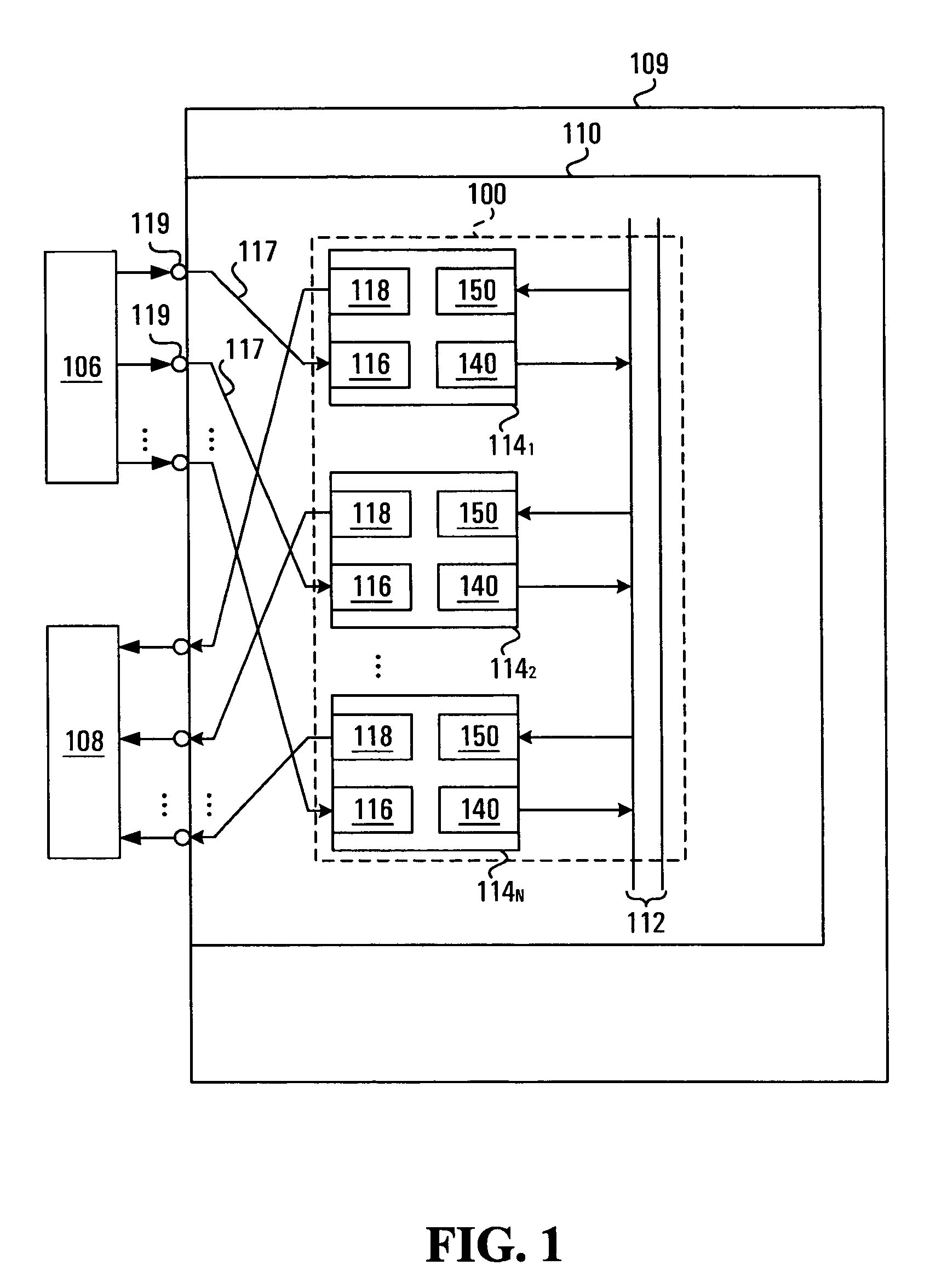
[0039]With reference to FIG. 13, there is shown a packet switch 105, comprising one or more line cards 106, 108, also referred to in the art as tributary cards. The line cards 106, 108 are connected at one end to a core network 107 or to other packet switches or routers. The line cards 106, 108 are connected at another end to one or more switch cards 109. Line cards 106 receive packets from the core network 107 and transmit them to the switch cards 109, while line cards 108 receive switched packets from the switch cards 109 and transmit them to the core network 107. In many embodiments, the line cards 106 are bi-directional. A mid-plane (not shown) may be provided to facilitate interconnection between the line cards 106, 108 and the switch card(s) 109.

[0040]Each switch card 109 has a plurality of input ports and a plurality of output ports. From the point of view of an individual switch card 109, the line cards 106 are input line cards as they supply packets to the input ports of th...


PUM


Abstract

A switch fabric implemented on a chip includes an array of cells and an I / O interface in communication with the array of cells for permitting exchange of data packets between said array of cells and components external to said array of cells. Each cell communicates with at least one other cell of the array, thereby permitting an exchange of data packets to take place between the cells of the array. Each cell includes a memory for receiving a data packet from another cell of the array as well as a control entity to control release of a data packet toward a selected destination cell of the array at least in part on a basis of a degree of occupancy of the memory in the destination cell. In this way, scheduling is distributed amongst the cells of the switch fabric.

Description

FIELD OF THE INVENTION[0001]The present invention relates generally to the switching of packets and, more particularly, to a high capacity switch fabric that can be implemented on a single semiconductor substrate.BACKGROUND OF THE INVENTION[0002]In a networking environment, it is necessary to route information groups (usually referred to as “packets”) between hosts along determined paths through the network. A routing algorithm is performed by the hosts in the network in order to determine the path to be followed by packets having various combinations of source and destination host. A path typically consists of a number of “hops” through the network, each such hop designating a host with a capacity to continue forwarding the packet along the determined path. The outcome of the routing algorithm thus depends on the state and topology of the network.[0003]Often, each packet has a protocol address and a label switch address. The protocol address identifies the destination host, while t...

Claims


Application Information

Patent Timeline
Patent Type & Authority Patents(United States)
IPC IPC(8): H04L12/28H04L12/56
CPCH04L49/15H04L49/1553H04L49/503H04L49/30H04L49/25H04L49/20H04L49/3009
Inventor NORMAN, RICHARD S.DE MARIA, MARCELOCOTE, SEBASTIENLANGLOIS, CARLHAUGHEY, JOHNBOUDREAULT, YVES
Owner CALLAHAN CELLULAR L L C
Learn More