Eureka AIR delivers breakthrough ideas for toughest innovation challenges, trusted by R&D personnel around the world.

Powered lower bobbin feed system for deflector type rotary braiding machines

a rotary braiding machine and lower bobbin technology, which is applied in the direction of braiding, textiles and papermaking, etc., can solve the problems of limiting the operating speed of rotary braiding machines, and achieve the effects of reducing unwanted stresses, reducing breakage, and improving operation

Inactive Publication Date: 2007-09-18
STOLBERGER
View PDF5 Cites 50 Cited by
  • Summary
  • Abstract
  • Description
  • Claims
  • Application Information

AI Technical Summary

Benefits of technology

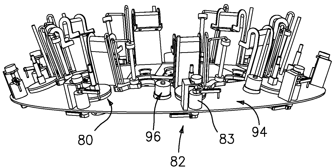
[0027]Applicants have improved the prior Wardwell braiding machines by replacing the conventionally used lower carrier members of those machines with a new Powered Lower Bobbin Feed (“PLBF”) system. The PLBF reduces the unwanted stresses placed on a filament of material being handled thereby, reducing breakage in the braiding process. The Powered Lower Bobbin Feed improves the operation of not only the Wardwell rotary braiding machines but also all other deflector type, circular braiding machines.
[0028]The PLBF concept eliminates or reduces the impulsive tension spikes set up by the deflection and feed process in current rotary braiding machines by uniquely controlling the lower bobbin filament feed. These tension spikes result from: the rapid rotational acceleration and deceleration required of the lower bobbin as a result of the feed process; the lever arm tension control and bobbin ratchet mechanism; and the shape of the filament deflector surface. Such failure limits the operating speed of rotary braiding machines, the minimum size of filament that can be braided effectively and / or the ability to maintain the quality of the braid produced. The PLBF concept can increase the working speed of circular braiding machines, or improve the uniformity of braided filaments generated by such machines at a given speed.

Problems solved by technology

Such failure limits the operating speed of rotary braiding machines, the minimum size of filament that can be braided effectively and / or the ability to maintain the quality of the braid produced.

Method used


Image

  • Powered lower bobbin feed system for deflector type rotary braiding machines
  • Powered lower bobbin feed system for deflector type rotary braiding machines
  • Powered lower bobbin feed system for deflector type rotary braiding machines

Examples


Embodiment Construction

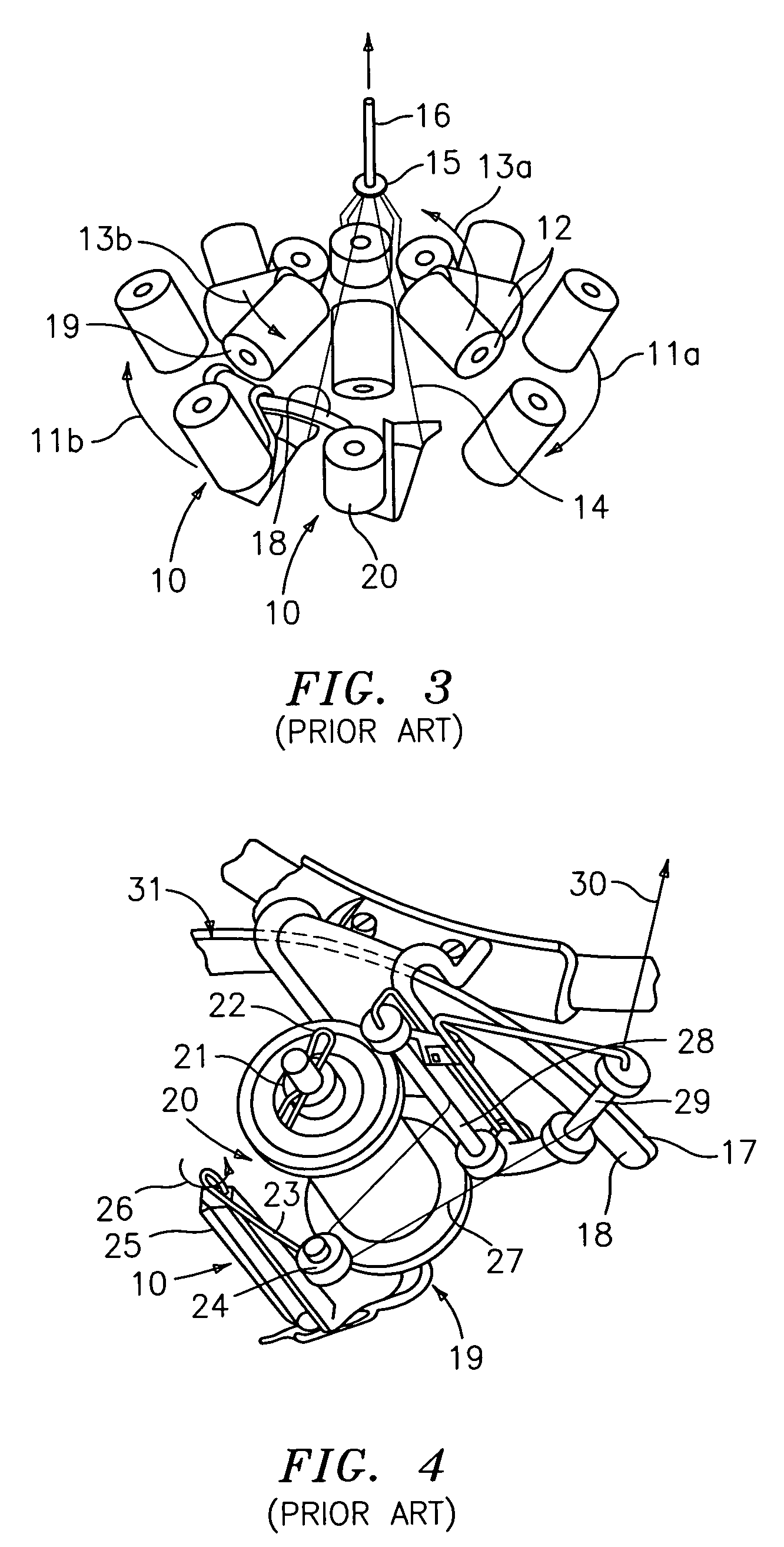
[0030]Applicants hereby incorporate by reference U.S. Pat. No. 1,423,587 entitled “YARN RETRIEVER FOR BRAIDING OR OTHER MACHINES” issued on Jul. 25, 1922. That patent, described in the Background section of the current application, was for the current Assignee's “Rapid Braider” rotary braiding machine. Current FIGS. 1, 7 and 2, including their unchanged reference numbers, are reproduced respectively from FIGS. 1-3 in U.S. Pat. No. 1,423,587. Legends however have been added for clarification.

[0031]The structure and operation of a typical Wardwell rotary braiding machine (e.g., the aforementioned Rapid Braider) is well known in the industry. It is also described in the instruction manuals available with such machines. One such manual, designated as “Wardwell Instruction Manual, Rapid Braiders,” has been provided as part of the Information Disclosure Statement associated with this application. FIG. 3 is an illustration adapted from a typical manual, and depicts diagrammatically the ope...


PUM


Abstract

A Powered Lower Bobbin Feed (“PLBF”) system is disclosed for improving the operation of deflector type rotary braiding machines, such as the Wardwell Rapid Braider. The PLBF eliminates or reduces the impulsive tension spikes set up by the deflection and feed process in current rotary braiding machines by uniquely controlling the lower bobbin filament feed. These tension spikes result from: the rapid rotational acceleration and deceleration required of the lower bobbin as a result of the feed process; the lever arm tension control and bobbin ratchet mechanism; and the shape of the filament deflector surface. Such failure limits the operating speed of rotary braiding machines, the minimum size of filament that can be braided effectively, or the ability to maintain the quality of the braid produced. By eliminating or reducing these spikes, the PLBF therefore can increase the working speed of circular braiding machines and improve the uniformity of braided filaments generated by such machines at a given speed. In the preferred embodiment, the PLBF comprises: a slip ring designed to provide power to the lower bobbins; a variable speed powered lower bobbin concept; a feedback control system for the bobbins to assure bobbin feed matches braid consumption; and an improved, more contoured, deflector surface to minimize feed tension spikes. The new contour can be created: by retrofitting existing deflectors with a spline; or, by making new deflectors that incorporate the overall contour of a retrofitted deflector.

Description

RELATED APPLICATION[0001]This application claims priority from U.S. Provisional Patent Application Ser. No. 60 / 647,187, filed Jan. 25, 2005.BACKGROUND OF THE INVENTION[0002]Braiding machines have long been known in the art for braiding-multiple filaments of materials, e.g., synthetics, plastics or metals, such as copper or stainless steel wire, at reasonably high production rates. One type of braiding machine, which is commonly referred to as an internal cam rotary braider, has been known to the art for many years. One of the best-known rotary (a.k.a. “circular”) braiders is the Wardwell Rapid Braider (hereinafter the “Rapid Braider” or “Wardwell rotary braiding machine”), made and sold by Wardwell Braiding Machine Company of Central Falls, R.I., U.S.A. (hereinafter “Wardwell”). Wardwell is the Assignee of the current application.[0003]Wardwell rotary braiding machines have been available in various sizes, depending on the number of filaments required in the final braided output, an...

Claims


Application Information

Patent Timeline
Patent Type & Authority Patents(United States)
IPC IPC(8): D04C3/42
CPCD04C3/44D04C3/14D04C3/38
Inventor PRESZ, JR., WALTER M.KOWALSKI, III, STANLEY
Owner STOLBERGER
Why Eureka
Eureka Blog
Learn More