Lithographic process window optimization under complex constraints on edge placement

a technology of complex constraints and edge placement, applied in the direction of photomechanical treatment originals, instruments, program control, etc., can solve the problems of excessive constraining of individual feature edges, computationally very difficult to reassess electrical performance after every iteration, etc., and achieve the effect of maximum efficiency

Inactive Publication Date: 2007-09-11
GLOBALFOUNDRIES INC
View PDF20 Cites 14 Cited by
  • Summary
  • Abstract
  • Description
  • Claims
  • Application Information

AI Technical Summary

Benefits of technology

where Dj is a constant. Eq.[3] assumes that there is no internal hierarchy in the circuit element under consideration, hence only two edges (xj+ and xj−) appear in each constraint. The x variables appearing in constraints of the eq.[3] form may actually involve different electrical elements of the circuit. More generally, eq.[3] could constrain the width of a feature, or the separation between features, or a more general requirement involving the edges of features in different process levels of the circuit.

Problems solved by technology

Unfortunately, it is computationally very difficult to reassess electrical performance after every iteration.
However, these conventional constraints have the drawback that they excessively constrain the individual feature edges from an electrical point of view, for example converting two electrically necessary constraints xj−xi>pj−pi−2sj and xj−xi>pj−pi+2ej into the four constraints listed in eqs.2a and 2b.

Method used


Image

  • Lithographic process window optimization under complex constraints on edge placement
  • Lithographic process window optimization under complex constraints on edge placement
  • Lithographic process window optimization under complex constraints on edge placement

Examples


Embodiment Construction

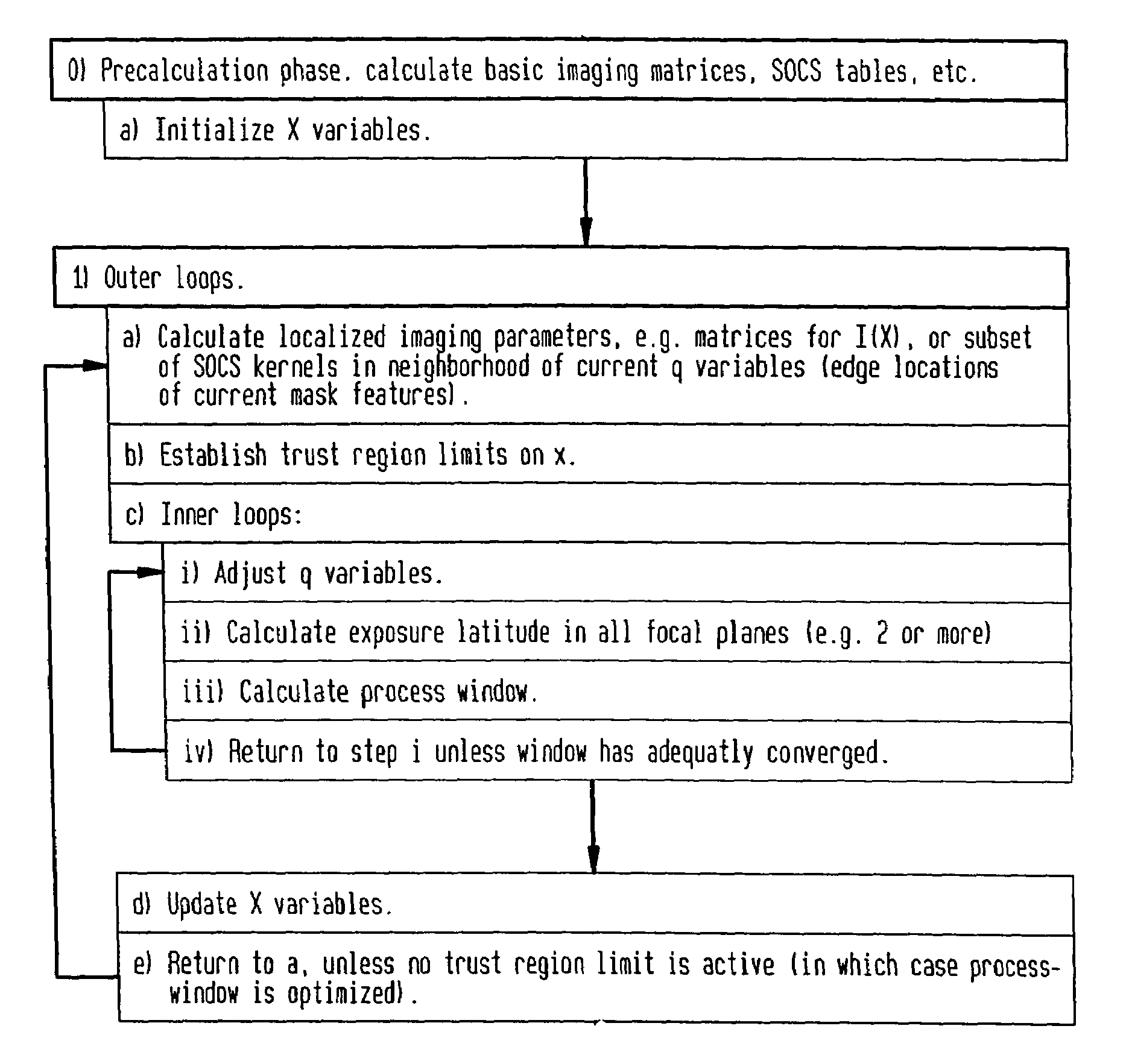
[0032]Rather than constraining feature edges so as to print within a fixed band of positions, as in conventional process window optimization, optimization is effected against more complex edge placement constraints which take the form of an interlinked set, whereby such interlinked constraints can grasp circuit performance requirements in an improved manner. These interlinked constraints can encompass as a special case the traditional constraints on feature edge position, but are more general. Despite this improved representation of circuit electrical properties, the optimization problem remains entirely in the lithographic domain; the goal of optimizing the lithographic process is retained in order to achieve acceptable circuit performance over the widest possible range of dose and focus variation. This new method continues to have the advantage that process window is determined purely through the calculation of image intensities and computationally equivalent quantities. As a resu...


PUM

PropertyMeasurementUnit
photosensitiveaaaaaaaaaa
light energyaaaaaaaaaa
shapesaaaaaaaaaa

Abstract

A method and system for layout optimization relative to lithographic process windows which facilitates lithographic constraints to be non-localized in order to impart a capability of printing a given circuit with a process window beyond the process windows which are attainable with conventional simplified design rules. Pursuant to the method and system, lithographic capability and process windows are maximized to satisfy local circuit requirements and in order to achieve a maximally efficient layout. In this connection, there is employed a method utilizing a generalized lithographic process window as a measure when layout optimization is extended to a degree beyond that achieved by the simple fixed design rules which are applied to the design rules obtained is the advantage that a lithographic process window is determined purely through the calculation of image intensities and slopes, and as a result, the method can be quite rapid in application because it is possible to take advantage of known methods for rapid calculation of image intensity, and because there is obviated the need for geometrical shape processing during optimization.

Description

BACKGROUND OF THE INVENTION[0001]1. Field of the Invention[0002]The present invention relates to a novel method and system for optimizing integrated circuit layouts in order to maximize a dynamically defined lithographic process in which lithographic tolerances are not applied at fixed edge locations, in order to achieve a larger process window for printing a functional circuit than is attainable with conventional design rules.[0003]Lithographic constraints are important factors in determining the efficiency of a circuit layout. In essence, lithographic constraints are conventionally determined by the generally limited capability of a lithographic process to successfully print edges at specified positions within tolerances. A lithographic process involves using a lithographic exposure tool to illuminate a lithographic mask from a range of directions, and focusing a projected image of the mask onto a photosensitive film that coats a partially fabricated integrated circuit on a wafer,...

Claims


Application Information

Patent Timeline
Patent Type & Authority Patents(United States)
IPC IPC(8): G06F17/50G03F1/14G03F7/20H01L21/00
CPCG03F1/144G03F1/36
Inventor HENG, FOOK-LUENLAVIN, MARK A.LEE, JIN-FUWOSTAPKO, DANIEL L.ROSENBLUTH, ALAN E.SEONG, NAKGEUON
Owner GLOBALFOUNDRIES INC
Why Eureka
Try Eureka