
Method and apparatus for branch prediction based on branch targets utilizing tag and data arrays

a branch prediction and target technology, applied in the field of digital processors, can solve the problems of high interrupt rate and intensive numeric computation, degrade performance, and high interrupt ra

Active Publication Date: 2007-09-04
ANALOG DEVICES INC
View PDF8 Cites 22 Cited by
  • Summary
  • Abstract
  • Description
  • Claims
  • Application Information

AI Technical Summary

Benefits of technology

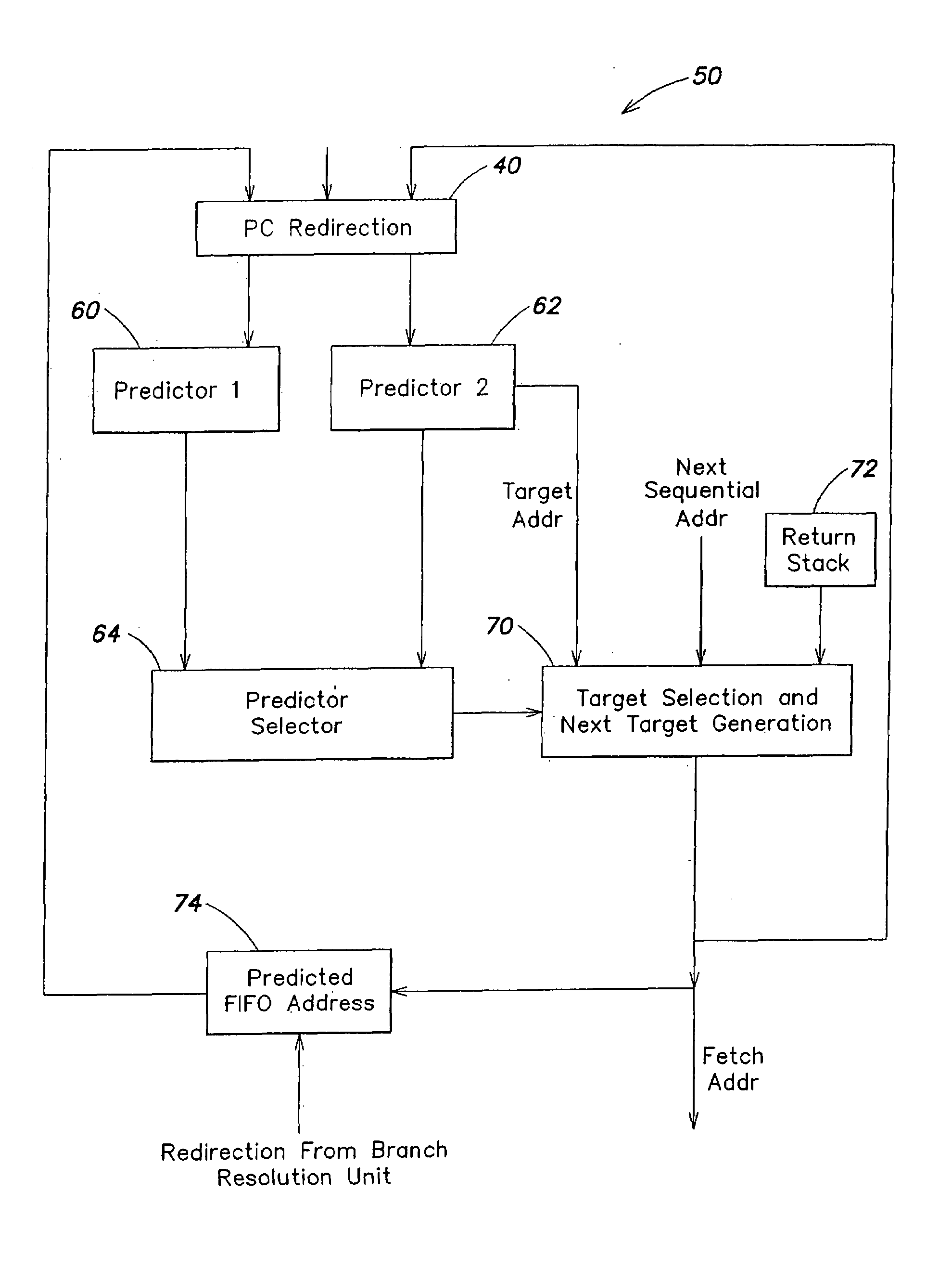
[0013]According to a further aspect of the invention, apparatus is provided for predicting branches in a program executed on a digital processor. The apparatus comprises a branch target buffer having a tag array and a data array, wherein each entry in the tag array provides an index to a corresponding entry in the data array, wherein a selected entry in the tag array stores information representative a branch target of a current branch instruction and a corresponding entry in the data array stores a taken branch target address of...

Problems solved by technology

Digital signal processor applications are typically characterized by real-time operation, high interrupt rates and intensive numeric computations.
In addition, digital signal processor applications tend to be intensive in memory access operations and to require the input and output of large quantities of data.
Notwithstanding the enhanced performance provided by pipelined architectures, certain program conditions may degrade performance.
For deeply pipelined architectures and programs having frequent branch instructions, the performance penalty is severe.
Prior art branch prediction techniques have had drawbacks and disadvantages including, but not limited to, excessive complexity and power consumption, and limited impact on performance.

Method used


Image

  • Method and apparatus for branch prediction based on branch targets utilizing tag and data arrays
  • Method and apparatus for branch prediction based on branch targets utilizing tag and data arrays
  • Method and apparatus for branch prediction based on branch targets utilizing tag and data arrays

Examples


Embodiment Construction

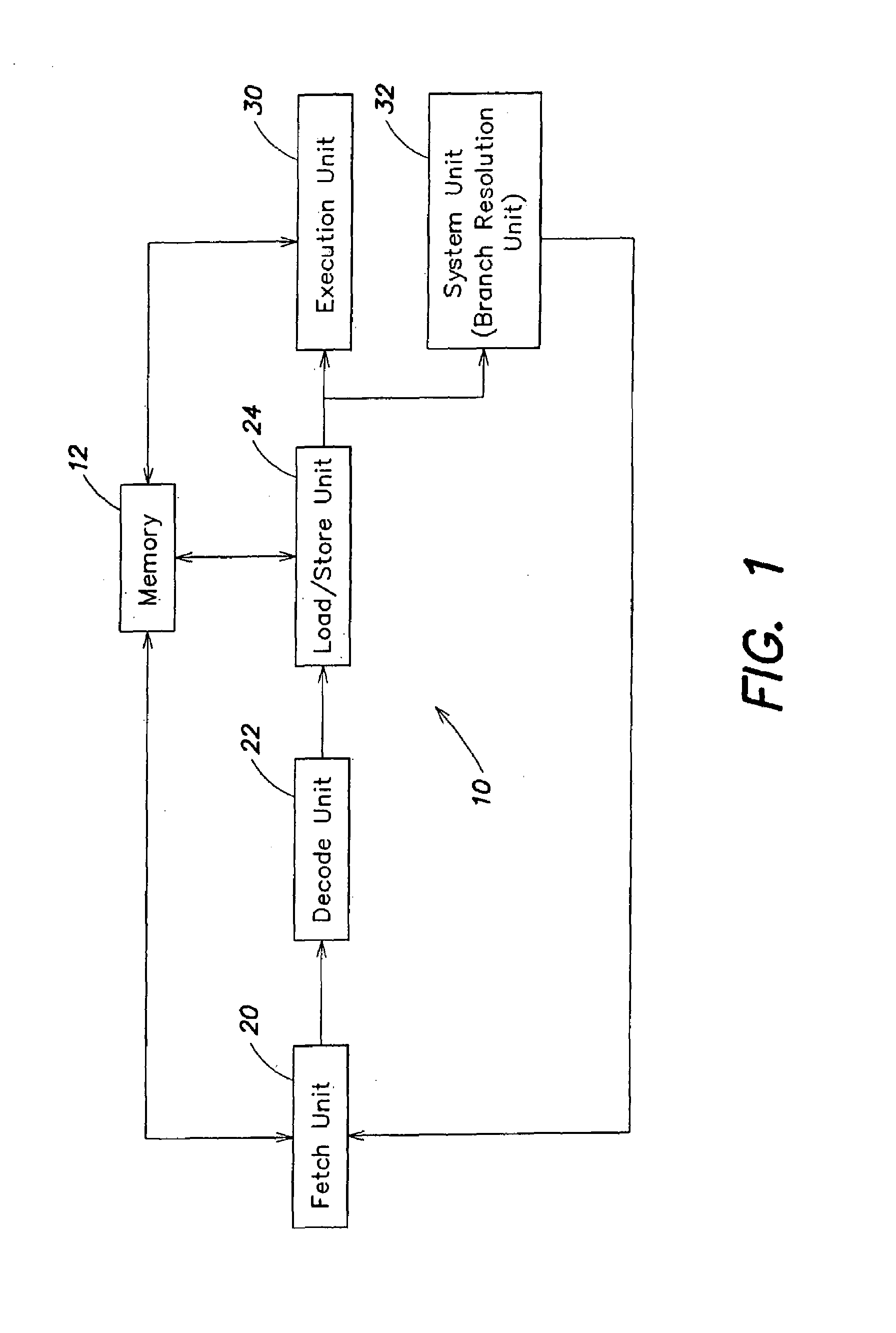
[0025]A block diagram of an embodiment of a digital signal processor (DSP) is shown in FIG. 1. The digital signal processor includes a computation core 10 and a memory 12. The computation core is the central processor of the DSP. The core 10 and the memory 12 may have a pipelined architecture, as described below. In this embodiment, core 10 includes an instruction fetch unit 20, an instruction decode unit 22, a load / store unit 24, an execution unit 30 and a system unit 32, which may include a branch resolution unit.

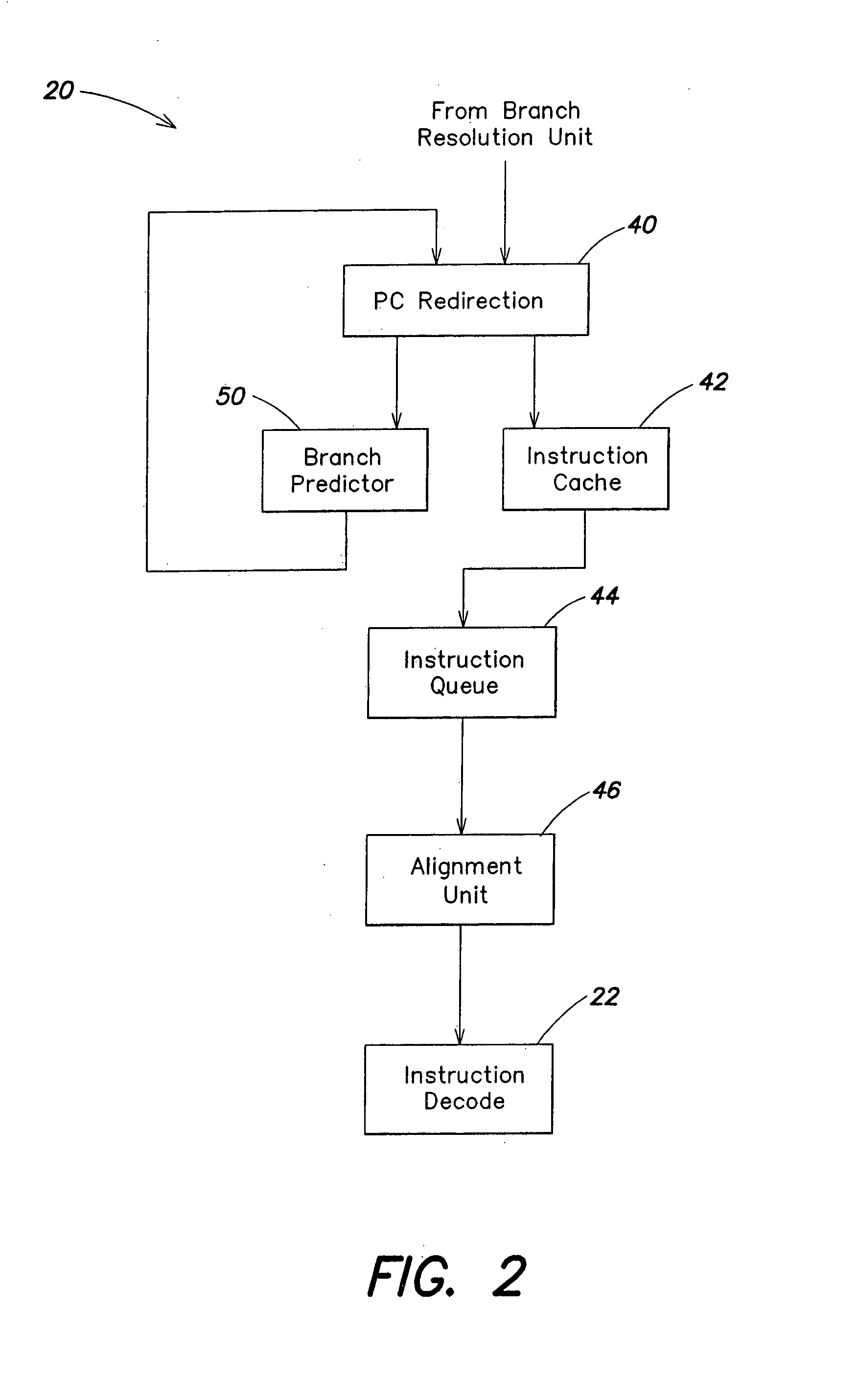
[0026]The instruction fetch unit 20 and the instruction decode unit 22 are discussed below. Load / store unit 24 controls access to memory 12. Memory read data may be transferred from memory 12 to a register file in execution unit 30. Memory write data may be transferred from the register file in execution unit 30 to memory 12. Instruction fetch unit 20 may access memory 12 in the case of an instruction cache miss in fetch unit 20. System unit 32 provides branch resolution ...


PUM


Abstract

Methods and apparatus are provided for branch prediction in a digital processor. A method includes providing a branch target buffer having a tag array and a data array, wherein each entry in the tag array provides an index to a corresponding entry in the data array, storing in a selected entry in the tag array information representative of a branch target of a current branch instruction, storing in a corresponding entry in the data array information representative of a branch target of a next branch instruction, and providing the information representative of the branch target of the next branch instruction in response to a match to an entry in the tag array. The information representative of the branch target of the next branch instruction may include a taken branch target address of the next branch instruction and an offset value. The offset value may represent an address of a next sequential instruction following the next branch instruction.

Description

FIELD OF THE INVENTION[0001]This invention relates to digital processors and, more particularly, to methods and apparatus for improving digital processor performance by predicting branches based on branch targets.BACKGROUND OF THE INVENTION[0002]A digital signal computer, or digital signal processor (DSP), is a special purpose computer that is designed to optimize performance for digital signal processing applications, such as, for example, fast Fourier transforms, digital filters, image processing, signal processing in wireless systems, and speech recognition. Digital signal processor applications are typically characterized by real-time operation, high interrupt rates and intensive numeric computations. In addition, digital signal processor applications tend to be intensive in memory access operations and to require the input and output of large quantities of data. Digital signal processor architectures are typically optimized for performing such computations efficiently. In addit...

Claims


Application Information

Patent Timeline
IPC IPC(8): G06F9/42G06F9/38
CPCG06F9/3804G06F9/3844G06F9/3806A61P31/04
Inventor TRAN, THANG M.SINGH, RAVI PRATAPDURAISWAMY, DEEPAKANNAN, SRIKANTH
Owner ANALOG DEVICES INC
Learn More