Wedge loading mechanism for traction drives

a technology of traction drive and loading mechanism, which is applied in the direction of interengaging clutches, couplings, gearing, etc., can solve the problems of high breakaway torque, component wear, inefficient transmission of torque and power, etc., and achieve the effect of improving the efficiency of traction drive and improving the dynamic stability of traction driv

Inactive Publication Date: 2007-09-04
THE TIMKEN CO
View PDF23 Cites 4 Cited by
  • Summary
  • Abstract
  • Description
  • Claims
  • Application Information

AI Technical Summary

Benefits of technology

[0018]For traction drives restricted to operate under small wedge angles, the drive is unnecessarily overloaded. This could lead to a low transmission efficiency and short service life.
[0029]The present invention provides a loading mechanism that allows for a traction drive to operate under a small wedge angle without having the traction drive become unnecessarily loaded thereby improving the efficiency of the traction drive. The present traction drive also provides a loading mechanism that improves the dynamic stability of the traction drive and which offers protection when the drive is overloaded.

Problems solved by technology

However, these devices sometimes tend to overload rollers and raceways when the wedge angle is small resulting in inefficient transmission of torque and power.
The spin motion not only offsets the high-efficiency otherwise provided by the traction drive, but also causes component wear and high break away torque.
However, generating sufficient normal force at the contacts has been a challenge.
The pre-load generated by such means, in general, can not be adjusted during operation.
For partial load application, traction drives are unnecessarily overloaded.
This has negative impacts on transmission efficiency and service life.
This imposes a restriction to the traction drive design.

Method used


Image

  • Wedge loading mechanism for traction drives
  • Wedge loading mechanism for traction drives
  • Wedge loading mechanism for traction drives

Examples


Embodiment Construction

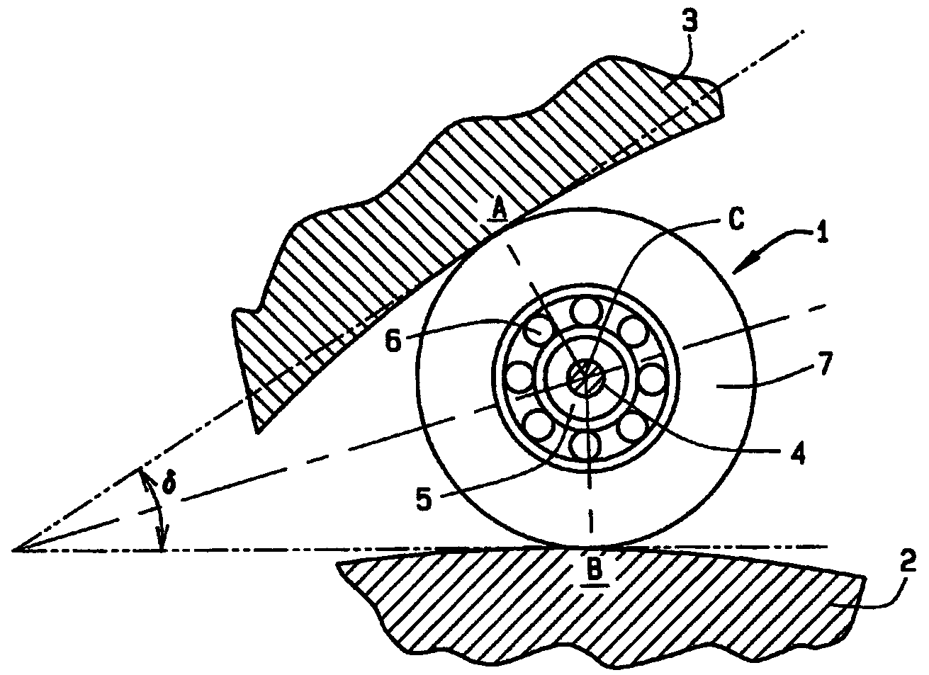
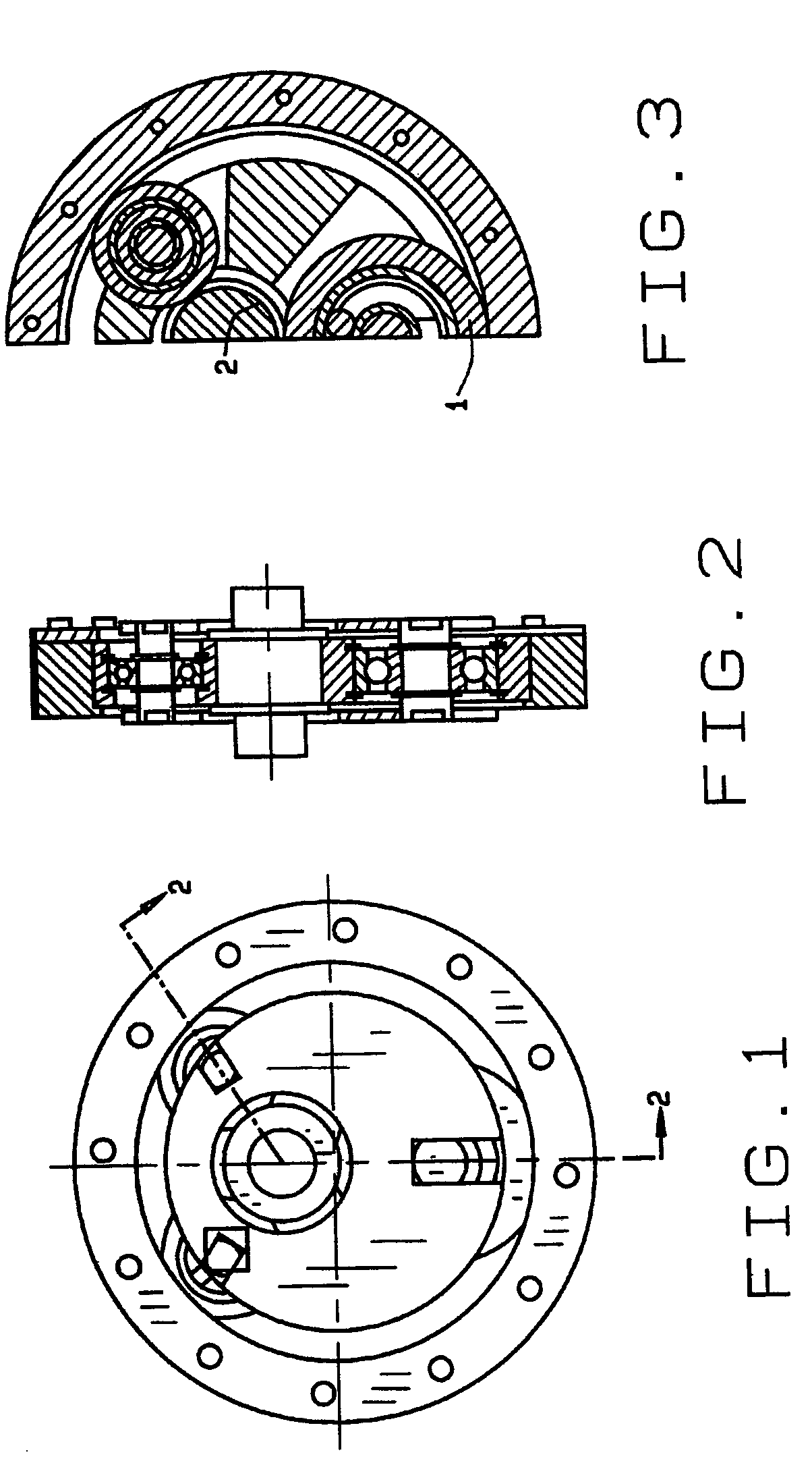
[0038]Now, referring to the drawings, FIG. 1, FIG. 2, and FIG. 3 depict a typical eccentric planetary traction drive having an eccentric sun roller and three planetary rollers, at least one of which is a loading planetary roller. In this typical traction drive, the present invention of a wedge loading mechanism 1 is a planetary roller that acts as the loading roller in this typical eccentric planetary traction drive. The wedge loading mechanism 1 is located between a first raceway 2, and a second raceway 3. The wedge loading mechanism 1 comprises a supporting shaft 4 (FIG. 5), a rubber insert 5, a bearing 6, and a loading roller ring 7. Shaft 4 is fixed to the wedge loading mechanism 1. The wedge loading mechanism 1 is positioned between and in contact with the first and second raceways 2 and 3. In FIG. 6, the tangential line OA at contact point A between the second raceway 3 and the wedge loading mechanism 1 lies at an angle of δ with respect to the tangential line OB at contact po...


PUM


Abstract

A wedge loading mechanism for an eccentric planetary traction drive in which a roller having a flexibly mounted shaft is positioned between two raceways forming a convergent wedge. Rotation of either of the two raceways wedges the roller within the convergent wedge squeezing the roller between the two raceways thereby transmitting rotational motion and torque between the two raceways. The flexibly mounted shaft generates differences between an effective supporting stiffness of the roller and an contact effective stiffness at the points where the roller contacts the two raceways. The difference in the effective stiffness allow the roller to operate efficiently at smaller convergent wedge angles.

Description

CROSS-REFERENCE TO RELATED APPLICATIONS[0001]This application is related to U.S. Provisional Patent Application No. 60 / 414,134 filed Sep. 27, 2002 from which priority is claimed.STATEMENT REGARDING FEDERALLY SPONSORED RESEARCH OR DEVELOPMENT[0002]Not applicable.BACKGROUND OF THE INVENTION[0003]1. Field of the Invention[0004]This invention relates in general to a wedge loading mechanism for traction drives, and, more particularly, to a wedge loading mechanism having an increased normal force for the contact points of a loading roller wedged between two raceways that form a convergent wedge.[0005]2. Description of Related Art[0006]Traction drives use frictional force to transmit torque and power. Because the power is transmitted between two smooth surfaces, often through a thin layer of lubricant, a traction drive possesses unique characteristics that are not readily attainable by gear drives. These characteristics include quietness, high-efficiency, high rotational accuracy, and zero...

Claims


Application Information

Patent Timeline
Patent Type & Authority Patents(United States)
IPC IPC(8): F16H13/06F16H13/14
CPCF16H13/14
Inventor AI, XIAOLAN
Owner THE TIMKEN CO
Why Eureka
Try Eureka