
Video system with de-motion-blur processing

a video system and motion blur technology, applied in the field of flat panel tvs, can solve the problems of tft-lcd panel displays, impede the development of lcd tvs, and generally slower response time of flat panel displays compared to crt displays, so as to improve the response time of flat panel displays

Active Publication Date: 2007-08-28
NOVATEK MICROELECTRONICS CORP
View PDF16 Cites 41 Cited by
  • Summary
  • Abstract
  • Description
  • Claims
  • Application Information

AI Technical Summary

Benefits of technology

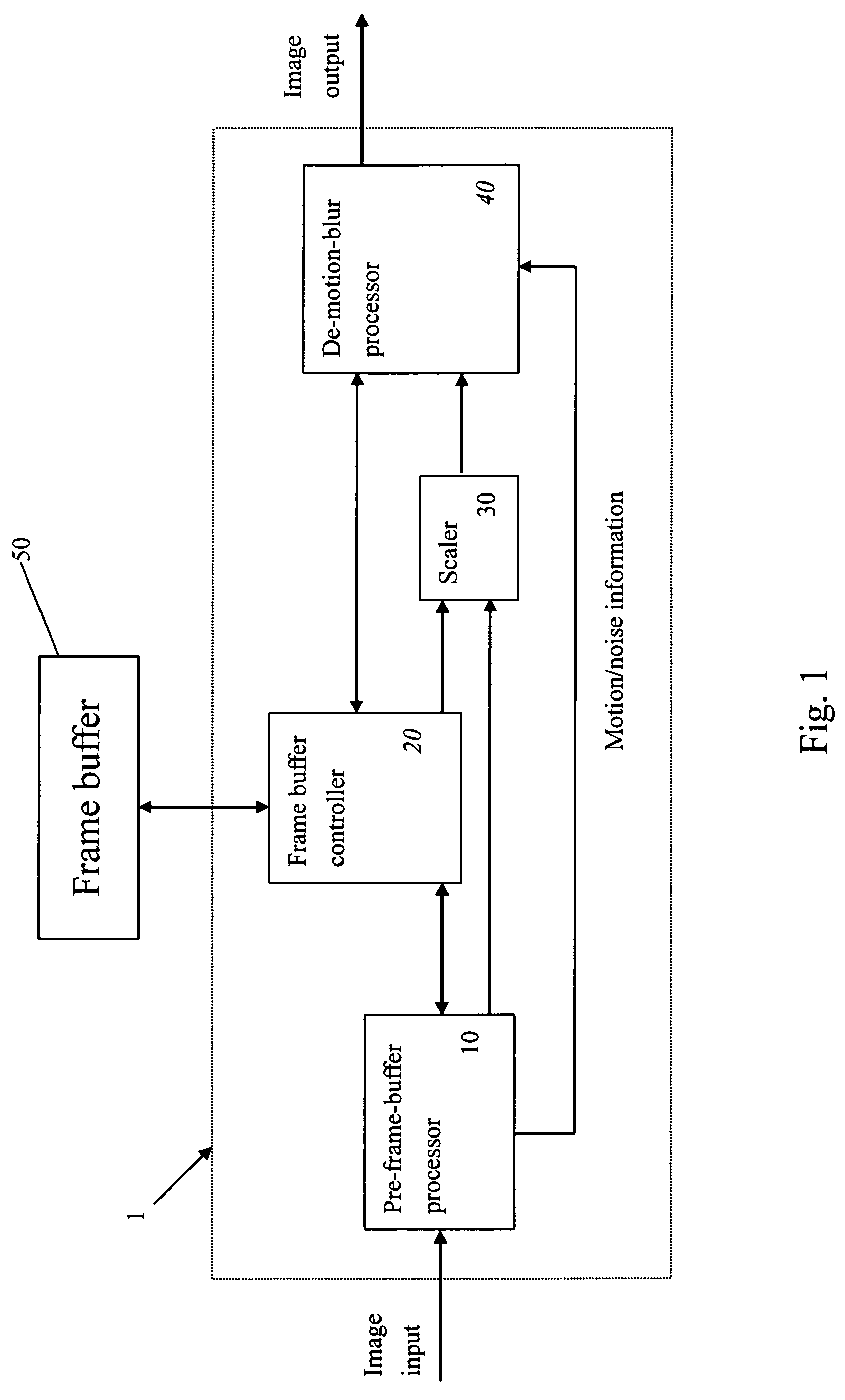
The present invention provides a video system for flat panel displays that improves response time, is cost-effective and performance-optimized. The video system includes a pre-frame-buffer processor, a frame buffer controller, a scaler, and a de-motion-blur processor. The pre-frame-buffer processor receives video signals for decoding and deinterlacing the video signals. The frame buffer controller provides one or more field delay to the video signals. The scaler converts the signals to a desired mode according to the specification of the flat panel display. The de-motion-blur processor compares current video signals with previous video signals and controls over driving to the flat panel display accordingly. The de-motion-blur processor also includes compression and decompression units, a motion and noise detector, and an over drive processing unit. The motion information is received by the de-motion-blur processor and used to determine the level of over driving. The technical effects of the invention include improved response time, cost-effectiveness, and better quality and rapid image processing.

Problems solved by technology

However, some of the flat panel displays, for example, TFT-LCD panel displays, are generally slower in the response time compared to the CRT displays.
This disadvantage hampers the development of the LCD TV, for which the display quality (especially motion blur) is highly concerned.

Method used


Image

  • Video system with de-motion-blur processing
  • Video system with de-motion-blur processing
  • Video system with de-motion-blur processing

Examples


Embodiment Construction

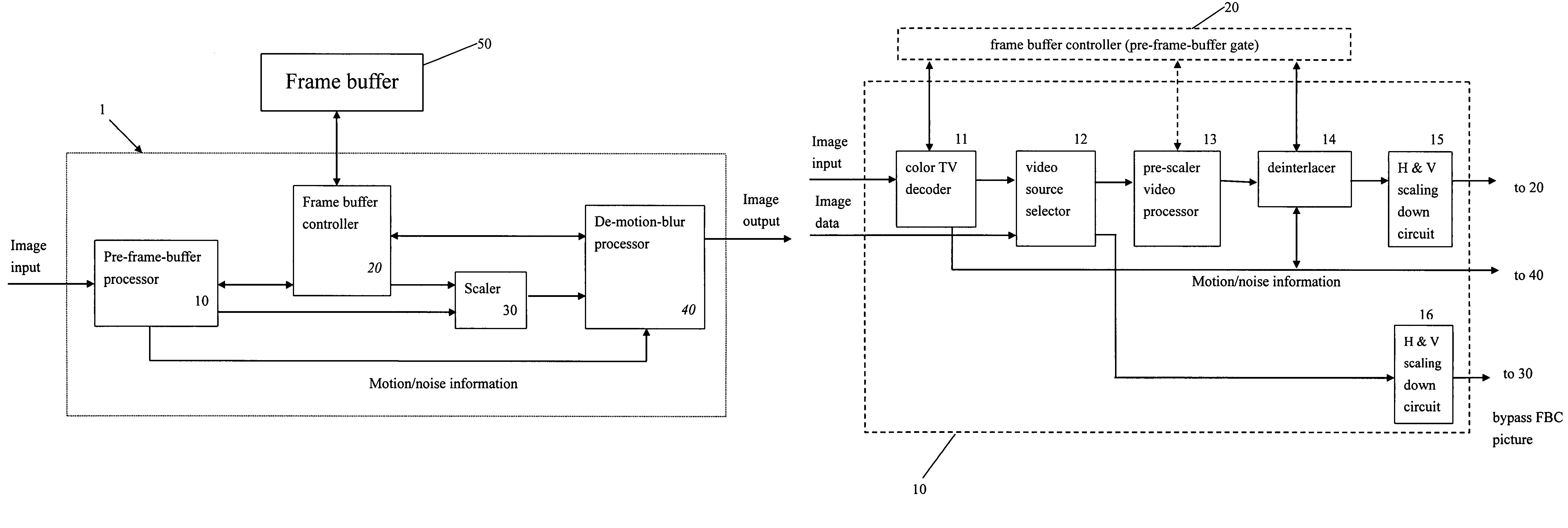
[0024]The present invention proposes a video system 1 for a flat display device. The video system 1 includes a pre-frame-buffer processor 10, a frame buffer controller 20, a scaler 30, and a de-motion-blur processor 40, as shown in FIG. 1. The flat display device can be (but not limited to) one of TFT-LCD panel, PDP (plasma display panel), OLED (organic light emitting display), and LCOS (liquid crystal on silicon).

[0025]In the system, the de-motion-blur processor 40 implements a novel over driving mechanism which uses one-frame or many-frame delay generated through YC-DPCM (Differential Pulse Code Modulation) compression and decompression units 41-43. The de-motion-blur processor 40 further comprises a motion and noise detector 45, and an over drive processing unit 44. The YC-DPCM compression unit performs de-correlation and entropy coding on Y and C (or luminance and chrominance) components separately.

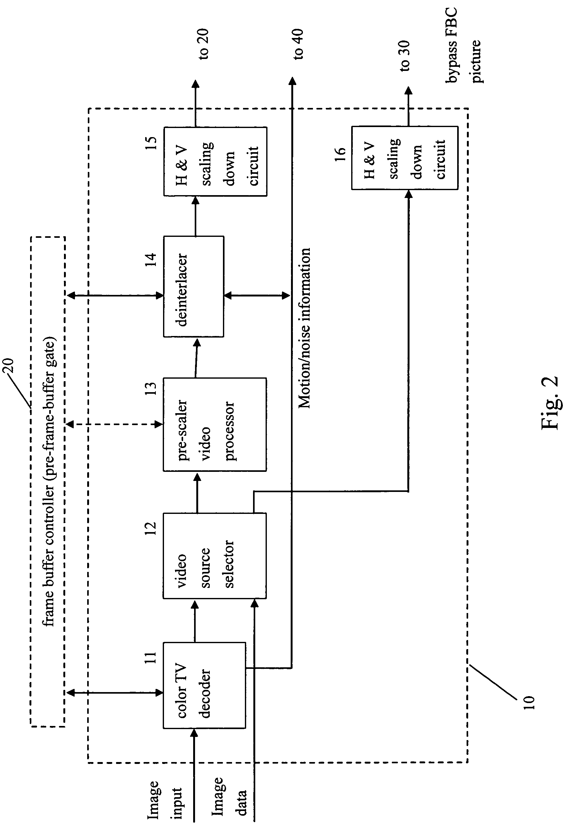
[0026]The pre-frame-buffer processor 10 has the functions of color TV decoding an...


PUM


Abstract

A video system that performs TV signal decoding, deinterlacing, and de-motion-blurring for progressive scan flat panel display is introduced. The system embeds a frame buffer and a scaler for conducting format and resolution conversions for display panels of different sizes. The output of the scaler is sent to a de-motion-blur processor for reducing the blurriness due to the motion of image objects and the slow response time of flat panel display devices. The de-motion-blur processor gets the motion and noise indication signal from scaler or the pre-frame-buffer video processor. Based on the motion and noise information and the information of temporal difference, the de-motion-blur processor performs over driving for the display panel interface and improves the rising and falling response time of the flat panel display. The decoding, deinterlacing, and de-motion-blur processing share the same frame buffer controller so the entire system can be optimized in cost and performance.

Description

BACKGROUND OF THE INVENTION[0001]1. Field of the Invention[0002]The present invention relates to the flat panel TV (especially the LCD TV) display system, and more specifically to a video system for improving the response time and reducing the motion-blur of the panel display.[0003]2. Description of Prior Art[0004]The development of flat panel displays has been accelerated. In the current display market, flat panel displays are gradually replacing the traditional CRT displays. However, some of the flat panel displays, for example, TFT-LCD panel displays, are generally slower in the response time compared to the CRT displays. This disadvantage hampers the development of the LCD TV, for which the display quality (especially motion blur) is highly concerned.[0005]To improve the quality of motion picture on the flat panel (especially TFT-LCDs), various driving techniques have been introduced. Among them, the over driving method is well known as the effective scheme for improving the res...

Claims


Application Information

Patent Timeline
Patent Type & Authority Patents(United States)
IPC IPC(8): H04N3/14G06F13/18G06K9/40G09G5/39G06T5/00H04N5/44
CPCH04N7/012G06T5/003G06T5/50H04N7/0112G06T2207/10016G06T2207/20201G06T5/73
Inventor CHUANG, CHUN-HSIUNGCHENG, CHIEN-HSUNWEN, SHIH-SUNGWANG, CHI-CHUAN
Owner NOVATEK MICROELECTRONICS CORP
Learn More