
Assembly for and a method of feeding and milking animals

a technology of assembly and milking animal, which is applied in the field of feeding and milking assemblies, can solve the problems of limiting the freedom of movement of dairy animals, animal being unpleasant to be milked in a closed area, and generally not being free to board the platform

Inactive Publication Date: 2007-08-28
LELY ENTERPRISES
View PDF31 Cites 17 Cited by
  • Summary
  • Abstract
  • Description
  • Claims
  • Application Information

AI Technical Summary

Benefits of technology

"The present invention provides an assembly for feeding and milking animals that includes a movable feed platform, a drive unit for the platform, and a number of feeding places. The assembly also includes an entrance and an exit for the animals, with the entrance being free from a closing device and having a sufficient width to allow several animals to simultaneously access the platform. The assembly promotes animal health, increases milk production, and improves animal comfort. It also allows for simultaneous access to the platform for several animals, preventing hindering effects. The assembly may also include an area for the animals to move freely and an exit from the platform to this area, with the exit being free from a closing device. The deterring device may include a lowered ceiling or a closing device, such as a curtain or lamellas, to prevent animals from crossing the transition unintentionally. The assembly may also include a control unit to synchronize the closing device with the drive unit of the feed platform."

Problems solved by technology

Additionally, the animals are generally not free to board the platform themselves but must be led or driven there by a herdsman or the like.
Such devices may suffer from the disadvantage that a dairy animal finds it unpleasant to be milked in a closed area, such as the stalls provided on the platform which limit the freedom of movement of a dairy animal to a high extent.
Furthermore, dairy animals appear to experience walking to and boarding the platform as unpleasant and may therefore by very unwilling to be led to or from the platform, which may result in problems to get an animal onto or from the platform, leading to insufficient occupation of the platform and thus reduced milk production.
In addition some animals may find the extreme long stay on the platform as unpleasant, as a result of which they might be very unwilling to be led to the platform.
In addition the assembly known from FR-A-2,649,858 also suffers from the disadvantage that a dairy animal to be milked is in a closed area, such as the stalls provided on the platform disclosed therein which limit the freedom of movement of a dairy animal to a high extent.
Each stall is closed by two gates, so that this also restricts the free movement of animals since an animal has to board the platform at a specific position.
Furthermore, dairy animals appear to experience walking to and boarding the platform as unpleasant and may therefore by very unwilling to be led to the platform, which may result in problems to get an animal onto or from the platform, leading to insufficient occupation of the platform and thus reduced milk production.
Although this known method may be expected to provide an enhanced efficiency when milking large herds, it has a number of drawbacks limiting its efficiency.
It has been found that the use of automatic driving devices leads to unrest with some of the dairy animals, and these animals may then be inclined to consider the platform as unpleasant.
This unrest will not only result in a reduced milk yield with some animals, but these animals will also be inclined not to go to the platform voluntarily.
This may lead to further unrest and to insufficient feed consumption, which is undesirable, of course.
A further drawback of this known method is that the dairy animals are not able to go voluntarily to the platform for being milked.

Method used


Image

  • Assembly for and a method of feeding and milking animals
  • Assembly for and a method of feeding and milking animals
  • Assembly for and a method of feeding and milking animals

Examples


first embodiment

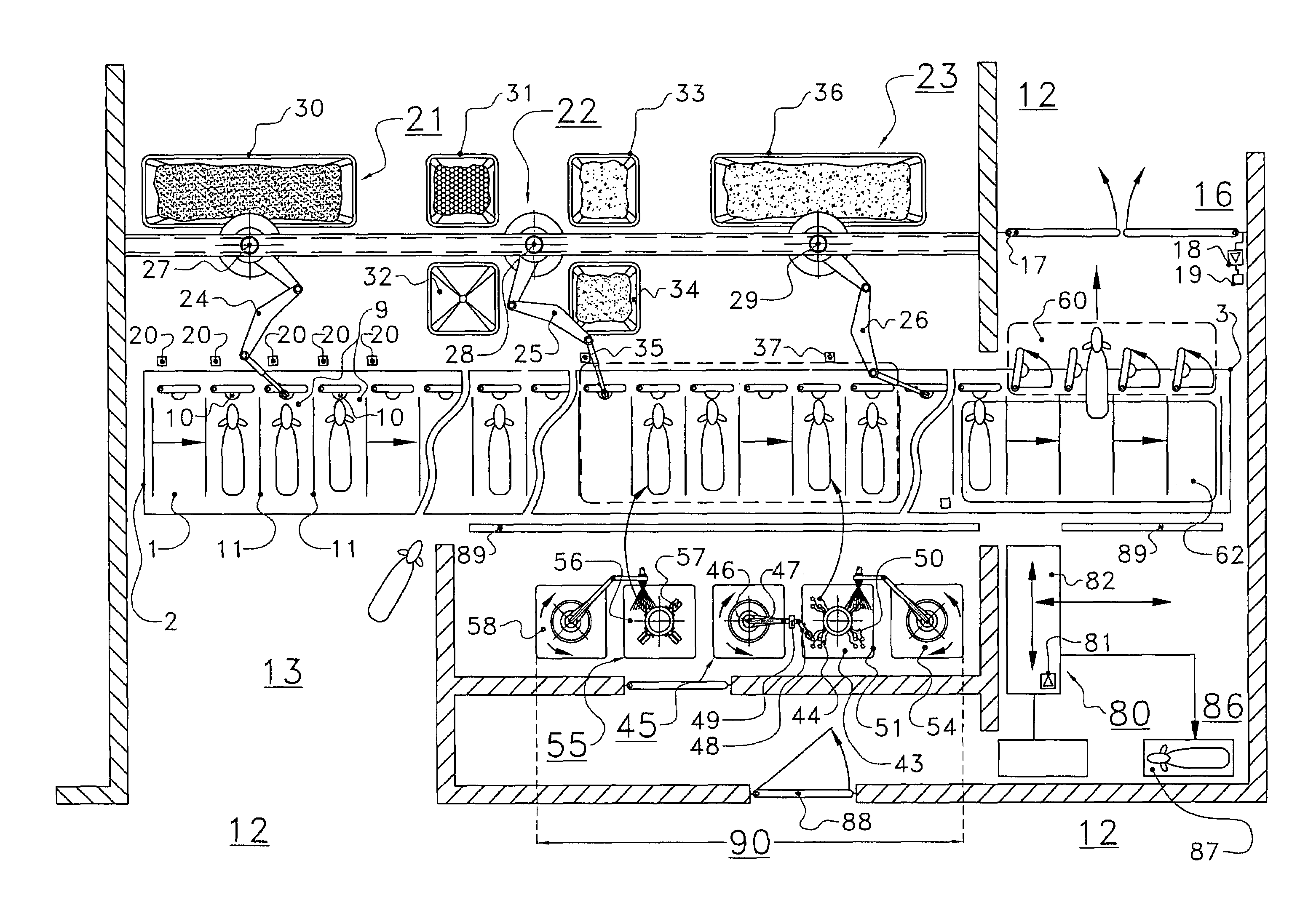
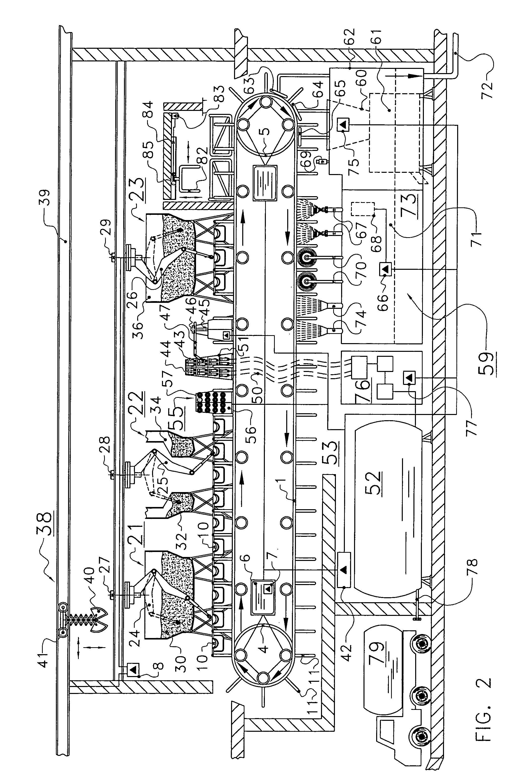
[0208]FIG. 1 shows diagrammatically in plan view and FIG. 2 shows diagrammatically in side view an assembly for feeding and milking animals, such as for example goats or cows, according to the invention. The invention will be described hereinafter with reference to cows, although it is obvious that the invention is not limited thereto, but may also be applied to all other dairy animals.

[0209]In the first embodiment, the assembly comprises a feeding system with a movable feed platform 1. The movable platform 1 constitutes a straight path with an initial end 2 and a final end 3. As shown in FIG. 2, reversing rollers 4, 5 are disposed at the initial end 2 and at the final end 3, so that the movable platform 1 forms a closed path.

[0210]It will be obvious that the movable platform 1 may also assume other forms than a straight path. As will be described hereinafter with reference to other embodiments, the movable platform may be disc-shaped or annular. However, the movable platform may al...

second embodiment

[0269]FIG. 3 is a diagrammatic plan view of a part of an assembly according to the invention. In this embodiment, the movable feed platform 91 is substantially disc-shaped. The feed platform 91 is provided with separation means 92 for partially separating cows. The separation means 92 adjoin a cow only on one side, so that a cow is not confined by the separation means 92. The feed platform 91 comprises feeding places, each having a feed trough 93 that is arranged in such a way that a cow is standing on the feed platform 91 under an angle with the radial. Owing to this, rotation of the shown feed platform 91 is only possible in one direction.

[0270]Via an entrance 94 and an exit 95 the cows are able to board or to debark from the feed platform 91 only one by one. In the entrance 94 there is arranged an animal-recognition device 96 by means of which the identity of a cow in the entrance 94 can be determined.

[0271]In the exit 95 there is also arranged an animal-recognition device 99 tha...

third embodiment

[0274]FIG. 4 is a diagrammatic plan view of a part of an assembly according to the invention. In this case the movable feed platform 106 is substantially annular. The feed platform 106 has a number of feeding places, each provided with its own feed trough 107 that is disposed in such a way that cows, when they are eating from the feed trough 107, are standing substantially radially on the feed platform 106, i.e. transverse to the usual direction of movement of the feed platform.

[0275]Analogously to the embodiment according to FIG. 1, the embodiment according to FIG. 4 has an entrance 108 that is sufficiently wide to enable simultaneous access of several cows to the feed platform 106. The entrance is freely accessible to cows.

[0276]The exit 110 also has a width that suffices to enable simultaneous exit of several cows from the feed platform 106. Like the entrance 108, the exit 110 is free from a closing device, so that cows are able to leave freely the feed platform 106.

[0277]The fee...


PUM


Abstract

An assembly for feeding and milking animals. The assembly is provided with a feeding system comprising a movable feed platform and a drive unit for driving the feed platform, a number of feeding places being provided on the feed platform. The assembly also includes a milking system for, in particular automatically, milking animals on the feed platform, which milking system comprises a number of sets of teat cups. An area where the animals are allowed to move freely communicates via an entrance with the feed platform, the width of the entrance being sufficiently large to enable simultaneous access of several animals to the feed platform. The entrance is free from a closing device.

Description

CROSS REFERENCE TO RELATED APPLICATIONS[0001]This application claims priority from Dutch application number 1024521 filed on 13 Oct. 2003, the contents of which are hereby incorporated by reference in their entirety.BACKGROUND OF THE INVENTION[0002]1. Field of the Invention[0003]The invention relates generally to feeding and milking assemblies and more particularly to feeding and milking assemblies in which the animals are located on a movable feed platform. The invention further relates to a method of milking an animal using such a movable feed platform.[0004]2. Description of the Related Art[0005]Methods and devices are known for milking animals in which the animals are located on movable platforms. Such known devices are generally provided with individual stalls or confining elements to prevent movement of the animals on the platform. Additionally, the animals are generally not free to board the platform themselves but must be led or driven there by a herdsman or the like. In cer...

Claims


Application Information

Patent Timeline
Patent Type & Authority Patents(United States)
IPC IPC(8): A01J5/003A01J5/017A01J7/04A01K1/12A01K5/02
CPCA01J5/017A01J5/0175A01J7/04A01K1/12A01K1/126A01K5/02
Inventor VAN DEN BERG, KARELBOS, GREORGIUS RUDOLPHIUS
Owner LELY ENTERPRISES
Learn More