
Systems and methods for biosensing and microresonator sensors for same

a microresonator and biosensor technology, applied in the field of systems and methods for detecting bacteria, can solve the problems of inability to distinguish between bacteria-surface bound lps and free (soluble) lps in solution, require highly trained laboratory personnel, and require days to obtain, and achieve the effect of less expensive and rapid results

Inactive Publication Date: 2007-08-14
3M INNOVATIVE PROPERTIES CO
View PDF49 Cites 25 Cited by
  • Summary
  • Abstract
  • Description
  • Claims
  • Application Information

AI Technical Summary

Benefits of technology

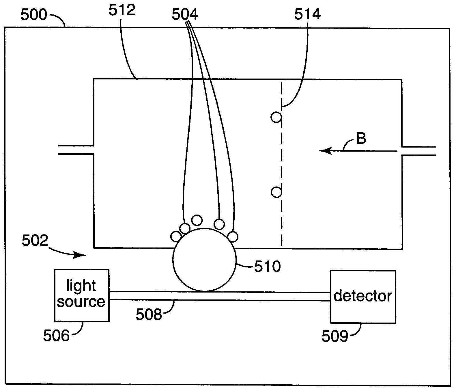
The present invention provides a method and apparatus for detecting biological species, such as bacteria, viruses, spores, proteins, and DNA and RNA strands, that are sensitive, less expensive, and produce results quickly. The invention involves a sensing chamber with a biosensor unit, a filter, and an analyte solution. The analyte solution interacts with the biosensor unit before reaching the filter, and the analyte on the surface of the biosensor is detected. The invention also includes a microresonator sensor apparatus that uses probe light and a microcavity resonator to detect the analyte. The apparatus includes a light source, a probe waveguide, a microcavity resonator, a detector unit, and a signal waveguide. The signal light reflector reflects signal light in the signal waveguide towards the detector unit. Overall, the invention provides a more efficient and effective method for detecting biological species.

Problems solved by technology

While these methods provide a desired level of sensitivity, they require highly trained laboratory personnel and typically need days to obtain results.
LAL cannot, however, distinguish between bacteria-surface bound LPS and free (soluble) LPS in solution.
The separation of soluble LPS from intact bacteria is a very challenging issue.

Method used


Image

  • Systems and methods for biosensing and microresonator sensors for same
  • Systems and methods for biosensing and microresonator sensors for same
  • Systems and methods for biosensing and microresonator sensors for same

Examples


experiment b

io, Low Concentration

[0086]At lower concentrations, however, the recovery ratio is less than when the concentration is 107 cells / ml. For example, at a concentration of 104 cells / ml, the recovery ratio fell to 24%. This reduction in recovery ratio was attributed, at least in part, to the dead volume caused by the adsorption of bacteria to the filter membrane. It was found that the recovery ratio increased when filters with a smaller area were used. For example, when the filter diameter was reduced to 13 mm, the recovery ratio increased to 53% (on average for three experiments, see Tables II–IV below). It should be noted that in actual microsphere biosensor chambers, the filter diameter may be as small as 1 mm, resulting in an even smaller dead volume, and increased recovery ratio.

[0087]Tables II–IV show the recovery results for each 1 ml backflow when the Staph Aureus concentration is varied with a value of about 104 cells / ml. For these experiments, the filters were Acrodisc® syringe...


PUM

PropertyMeasurementUnit
pore sizeaaaaaaaaaa
pore sizeaaaaaaaaaa
pore sizeaaaaaaaaaa

Abstract

A biosensor system is provided for detecting biological species such as bacteria, proteins, viruses, spores and DNA or RNA. The biosensor system may also be able to distinguish between Gram positive and Gram negative bacteria. In some embodiments, the analyte solution flows past a detector surface to a filter, which traps the analyte. The analyte is then washed back past the detector surface, thus increasing the number of analyte species that become attached to the surface. The detector may include an optical microresonator that is optically coupled via waveguides to a light source and an optical detector. One of the waveguides may be provided with a wavelength selective reflector to increase the amount of probe light coupled into the microresonator or to increase the fraction of the signal light detected by the optical detector.

Description

FIELD OF THE INVENTION[0001]The invention is directed generally to systems and methods for detecting bacteria, including optical sensors that use microresonators.BACKGROUND[0002]The detection of biological species is an important analytical technique in several industries, including the food industry, environmental monitoring, and health care, e.g. for the prevention of post-surgical infection. For example, traditional methods of detecting bacteria require the culturing of microorganisms. While these methods provide a desired level of sensitivity, they require highly trained laboratory personnel and typically need days to obtain results.[0003]Post-surgery infections constitute the most common infection for surgical patients. In many cases, bacteria still remain on the skin after the skin has been prepared for surgery. About 20% of the population have high bacteria counts on the skin, i.e. more than 1000 CFU cm−2 and represent those who are at greatest risk of infection. Accordingly,...

Claims


Application Information

Patent Timeline
Patent Type & Authority Patents(United States)
IPC IPC(8): G02B6/42G02B6/00G02B6/26
CPCC12Q1/6825G01N15/0618G01N21/6428G01N21/648G01N21/7746G01N2001/4088G01N2021/6421G01N2021/6439G01N2021/7786G02B6/12007G02B6/29341G02B6/4246G01N15/01C12Q2565/629C12Q1/70G02B6/26G02B6/42
Inventor GUO, CHUNMEIFAN, XUDONG
Owner 3M INNOVATIVE PROPERTIES CO
Learn More