
Multiple input data receiver for cable television systems

a multi-input, data receiver technology, applied in the field of multi-input data receivers for cable television systems, can solve the problems of delay in signal detection, jamming and/or disassembly of other inputs/paths, and inacceptable “noise funneling” to achieve the effect of reducing system response time, re-enabled monitoring of input ports, and reducing the response tim

Active Publication Date: 2007-08-07
VIAVI SOLUTIONS INC
View PDF16 Cites 4 Cited by
  • Summary
  • Abstract
  • Description
  • Claims
  • Application Information

AI Technical Summary

Benefits of technology

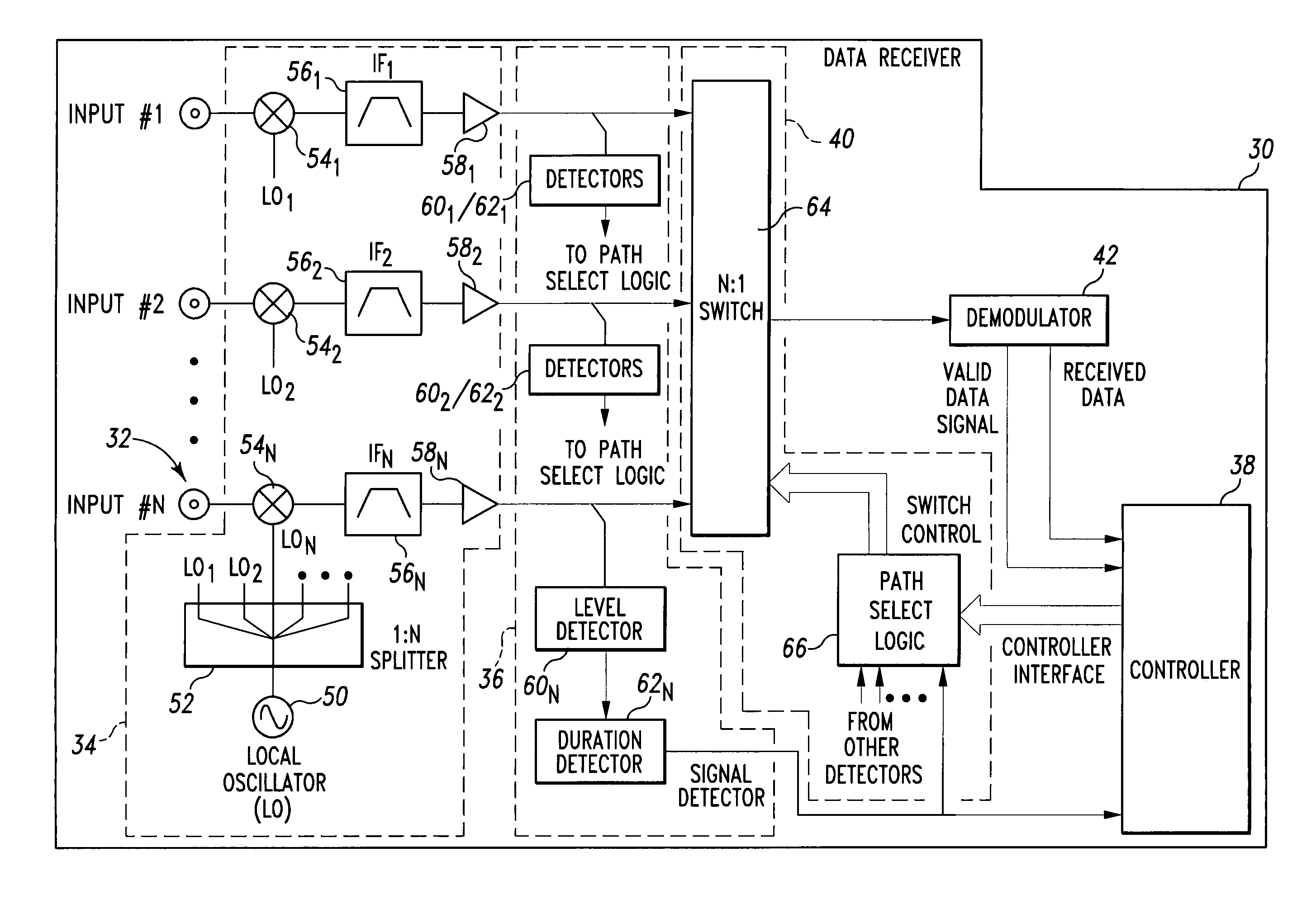
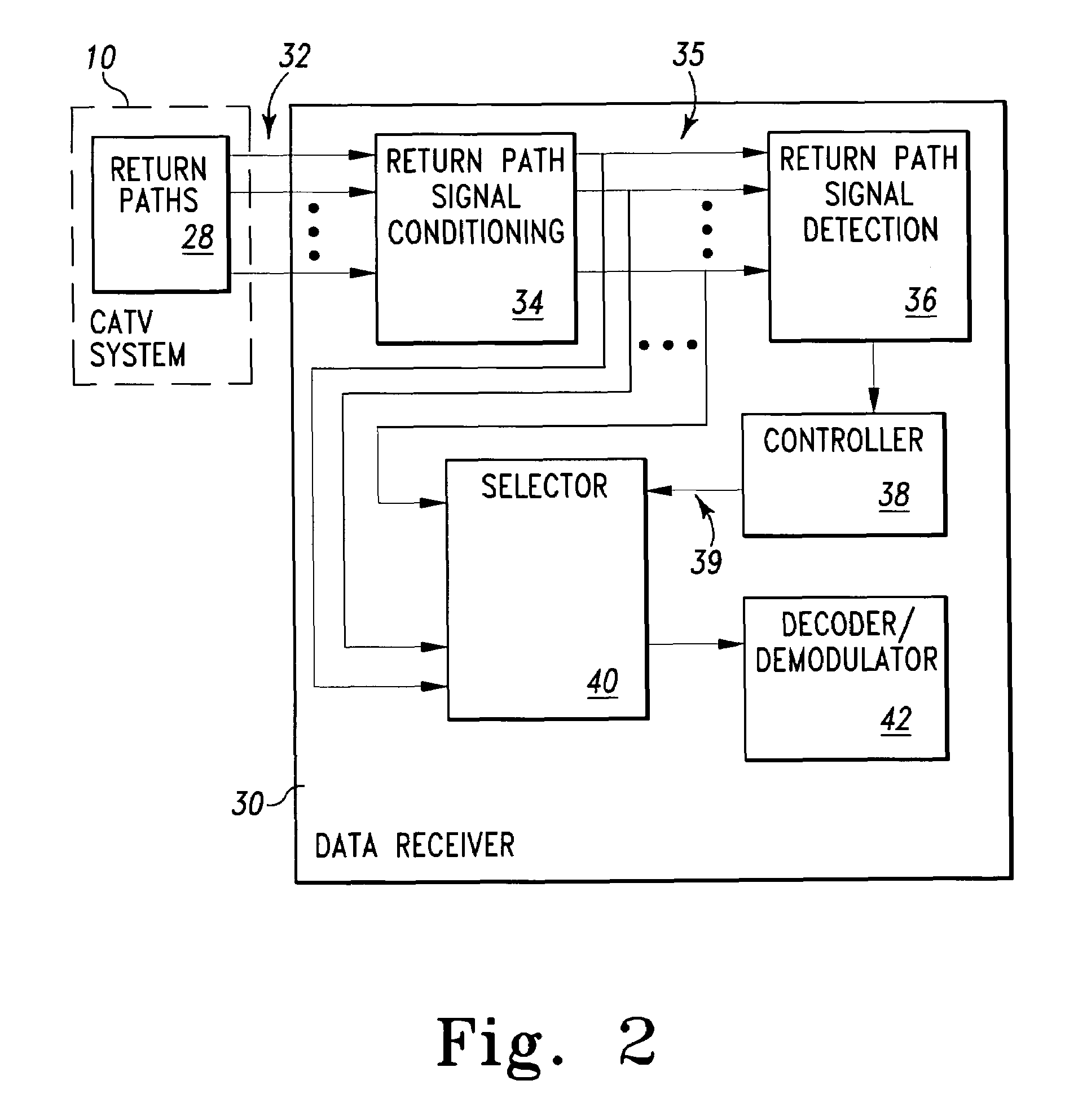
[0016]More particularly, the present invention is a data receiver for bi-directional cable television systems that monitors multiple return paths in parallel to detect and then receive and decode an appropriate return path signal. The data receiver monitors N different RF input ports tuned to a common frequency by a single local oscillator that is split N ways. The input signals are mixed into individual IF circuits. A level detector for each IF circuit is used to determine if a signal above a specific level is being received. A duration detector is coupled to each level detector to determine if the signal level is maintained for a minimum duration. These two detection stages reduce the likelihood of false detection due to noise bursts and other random signals.
[0020]It is appreciated that the present invention works for any fixed level data modulation schemes. By choosing an appropriate demodulator, any number of data signals can be received. In a multi-mode demodulator version, each port is configured for a different modulation scheme. For example, two ports could be configured for FSK, three ports for QPSK, one port for BPSK, etc. By using signal detect lines to inform the controller of the data receiver which port is active, the controller can appropriately configure or setup the demodulator. As an alternative, an “auto-sensing” demodulator can be used to automatically detect different modulation types / schemes and then decode them appropriately.
[0025]Also, since scanning is not necessary in the present invention, the present invention may be scaled up to any number of inputs, with no reduction in response time. Additionally, any input port or path may be shut off as necessary such as due to ingress or other unwanted signal or response. The present invention provides a means to quickly re-enable the monitoring of the input ports in the event that a false detection occurs. Simultaneous or parallel monitoring / receiving of all return paths minimizes system response time.

Problems solved by technology

In the past, when system problems arise, a service technician must go on-site to determine the source of the malfunction.
Combining all of the return paths, however, can result in unacceptable “noise funneling.” Also, with this configuration, an input / path with ingress can jam and / or disable the other inputs / paths.
A problem with this method is balancing out the “dwell” time on each input port with the speed of the detection hardware.
Each of the filters in a receiver causes a delay in signal detection.
Rapid scanning can also cause some signals to be missed.
It is easily discernable from the foregoing that previous known return path monitoring is deficient in various respects.

Method used


Image

  • Multiple input data receiver for cable television systems
  • Multiple input data receiver for cable television systems
  • Multiple input data receiver for cable television systems

Examples


Embodiment Construction

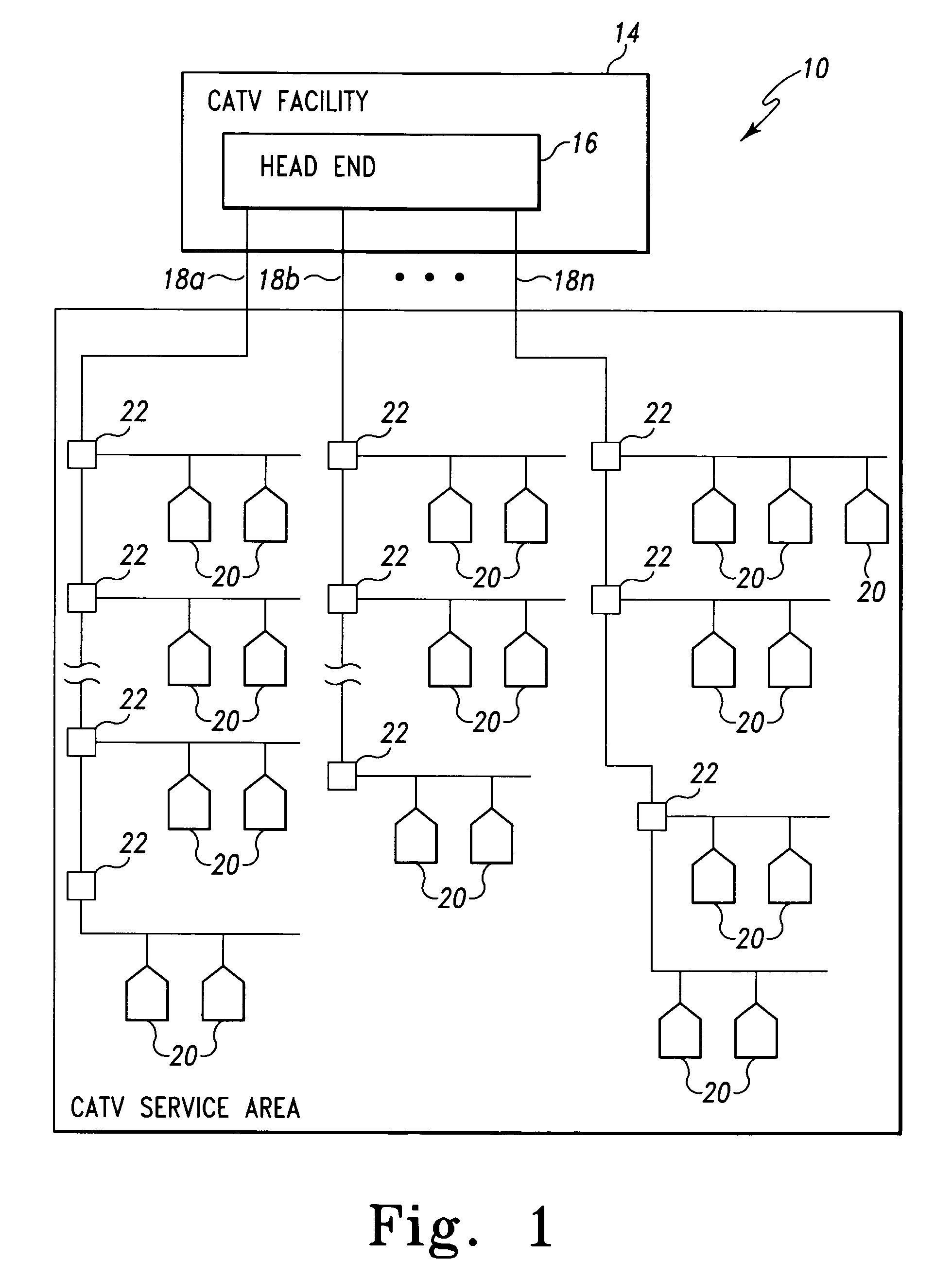
[0034]With reference now to FIG. 1, there is depicted a block diagram representation of a typical bi-directional television signal and data distribution system or network, generally designated 10. The bi-directional television signal and data distribution system 10 represents any same or similar bi-directional system anywhere in the world. Particularly, the bi-directional television signal and data distribution system 10 represents a bi-directional cable television (CATV) system that distributes, sends, or transmits television, data and / or entertainment signals (collectively, upstream originated signals) via a plurality of loops or runs of coaxial cable, fiber-optic cable, hybrid coaxial-fiber cable, and / or the like (collectively, coaxial cable) and receives data / signals (collectively, downstream originated signals) via the same coaxial cable or via a separate coaxial cable paralleling the upstream originated signal coaxial cable. Hereinafter, without limitation, the bi-directional ...


PUM


Abstract

A multiple input data receiver for bi-directional cable television (CATV) systems simultaneously monitors and selectively receives a return path signal on a plurality of return paths. When an appropriate data or signal transmission is detected on a return path, the corresponding return path is selected and then demodulated. The demodulated signal is appropriately decoded to yield signal data. Various tests and analyzing may be performed on the signal data. Simultaneous monitoring / receiving of all or a plurality of return paths minimizes system response time.

Description

FIELD OF THE INVENTION[0001]The present invention relates to data receivers for bi-directional cable television systems and, more particularly, to a data receiver for monitoring signals on a plurality of return paths of bi-directional cable television systems.DESCRIPTION OF THE PRIOR ART[0002]Cable television systems, often denoted CATV systems, are comprised of many miles of coaxial cable strung about a service area with amplifiers and other elements interspersed throughout as necessary. The CATV system carries a number of channels of television programming that typically include both audio and video information. The CATV system may carry analog signals, digital signals, and / or a combination of analog and digital signals. As well, supplemental information, such as closed captioning information and / or V-chip (rating) information may also be broadcast over a channel, with each channel having a unique channel frequency. Subscribers to the CATV system are connected to the coaxial cable...

Claims


Application Information

Patent Timeline
Patent Type & Authority Patents(United States)
IPC IPC(8): H04N7/173G06F15/00H03F1/26H04B1/00H04B15/00H04B7/00H04N21/239H04N21/24
CPCH04N7/17309H04N21/239H04N21/2408
Inventor HUNTER, DAVID R.
Owner VIAVI SOLUTIONS INC
Learn More