
Method for establishing a binaural communication link and binaural hearing devices

a technology of binaural communication and hearing devices, which is applied in the direction of ear supported sets, electrical transducers, electrical appliances, etc., can solve the problems of impaired binaural connections between the pair of hearing devices, high data compression, and high power consumption of the transmitter and the receiver, so as to achieve accurate pulling of the areas

Inactive Publication Date: 2007-08-07
SONOVA AG
View PDF19 Cites 22 Cited by
  • Summary
  • Abstract
  • Description
  • Claims
  • Application Information

AI Technical Summary

Benefits of technology

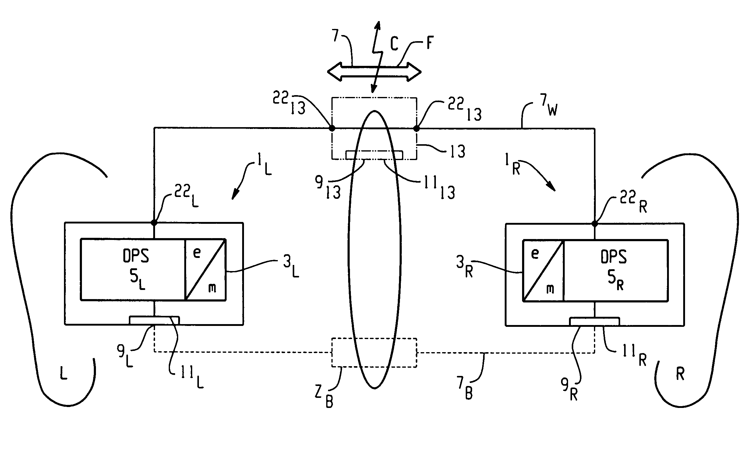
[0007]Thus the individual body with the respective body impedance is exploited as one of the said conductors so that there remains, in minimum, a single wire connection to be established between the hearing devices. Such a single wire connection may very easily be handled and plugged in at the respective hearing devices by the individual.
[0011]In a most preferred embodiment the advantage of having only one wire to be connected either directly between the hearing devices or from the respective hearing devices to an interconnected electronic unit is exploited by realising connection of the wire to the hearing devices and / or to such electronic unit by a magnetic attraction. This leads to most easily handable plugging. The wire with a respective magnetic plug at one or at both of its ends may just be brought adjacent to the respective plug area at the hearing device or at the electronic unit, Connection will be practically automatically installed by that wire end being magnetically pulled onto said plug area at the respective device.
[0014]In a further preferred mode said at least one wire is applied to at least one of the hearing devices and / or the electronic unit—mechanically—by magnetic attraction and—electrically —via a dielectric layer. Thereby a capacitive coupling is realised. By applying the wire to the at least one hearing device and / or electronic unit at both sides of the dielectric layer a conductive capacitance plate as e.g. of metal is established, thereby completing a capacitor structure. It is also possible to provide on both sides namely on the side of the hearing device or of the electronic unit, if provided, as well as on the side of the wire a dielectric layer. When such layers are joint once the connection is established, they form a dielectric double-layer. With provision of such dielectric layer or layers cleanability of the contact area is significantly improved e.g. on the side of the hearing device, where the dielectric layer may be part and be flush with the outer surface of the device's shell.
[0018]If necessary, by respective selection of polarities of magnets, on one hand on the hearing device or electronic unit, and, on the other hand, on the side of the wire, one can prevent that the wrong wire side is applied to a respective hearing device or electronic unit contact area.

Problems solved by technology

Today known binaural links between a pair of hearing devices are impaired by the severe requirements at hearing devices and thereby especially at hearing aid devices with respect to electric power consumption.
Thereby satisfyingly small receiving and transmission aerials may be used, but the power consumption for the transmitter and the receiver is considerable.
A communication link approach at lower transmission frequencies necessitates, whenever audio signals shall be transmitted via such link, relatively complex encoding and decoding procedures as e.g. MPEG-codec, so as to result in high compression of the data being transmitted.
Such encoding procedures nevertheless have the drawback of significant signal delay normally in excess of 50 msec and are therefore not suited for binaural communication between hearing devices as here a real-time signal processing is important.
Handling of a cable with two wires and especially of respective mini-plugs at the hearing devices is cumbersome for the individual, especially if such handling is performed as the hearing devices are already applied to the individual's ear.

Method used


Image

  • Method for establishing a binaural communication link and binaural hearing devices
  • Method for establishing a binaural communication link and binaural hearing devices
  • Method for establishing a binaural communication link and binaural hearing devices

Examples


Embodiment Construction

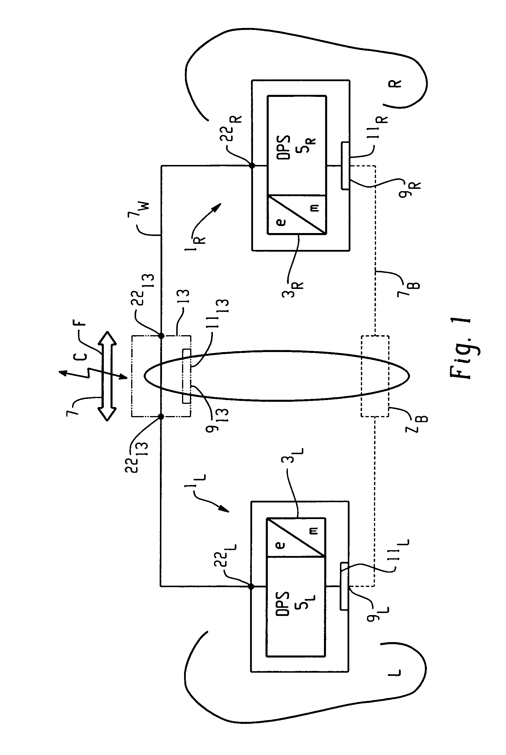
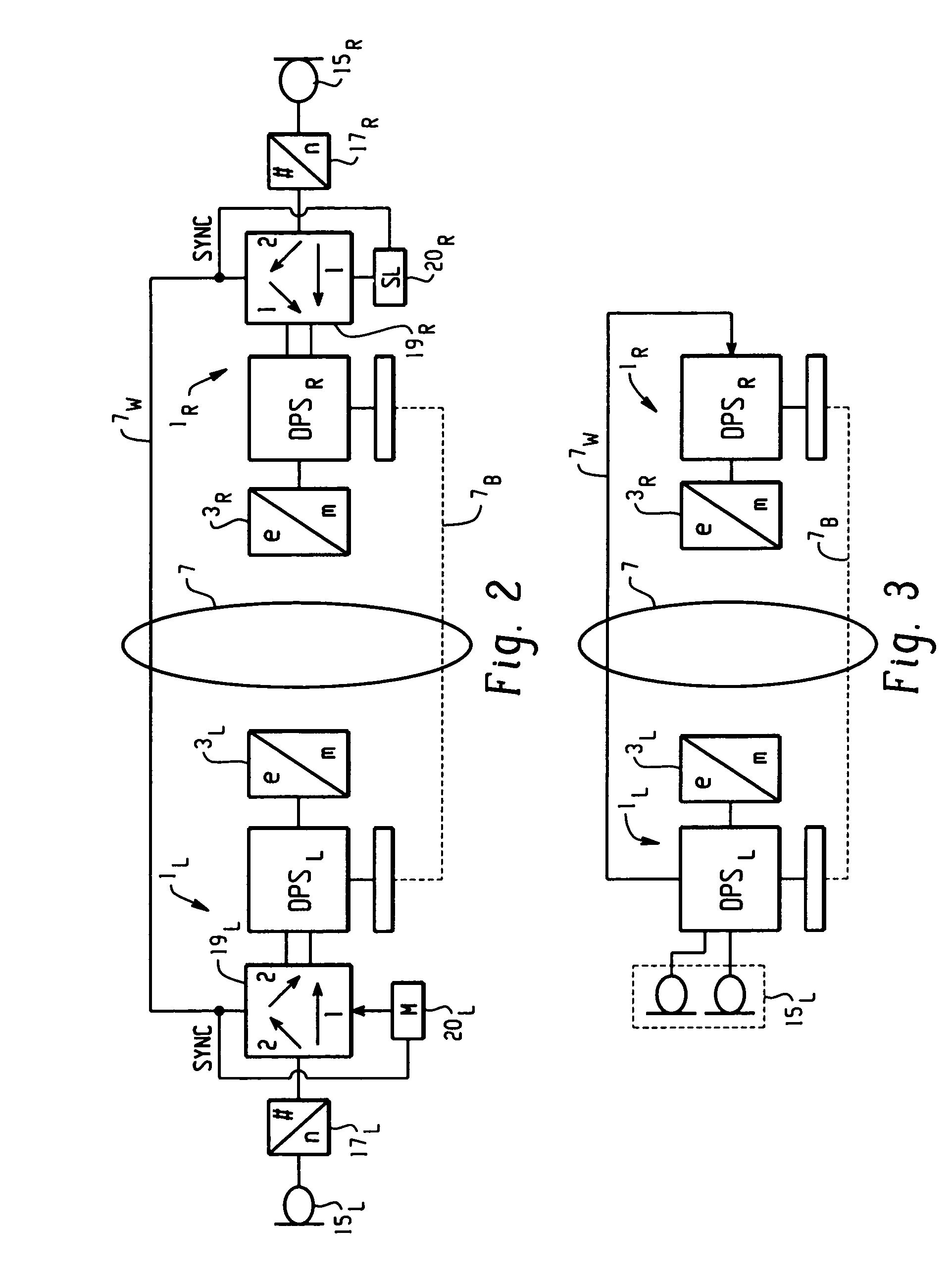
[0032]In FIG. 1 there is shown, in a most generic and simplified representation form, the principle of the method according to the present invention and, accordingly, a set of binaurally operated hearing devices. At the left side -L- and the right side -R- ear of an individual there is applied a left-ear hearing device 1L and respectively a right-ear device 1R. Conceived as active hearing devices, each of these devices comprises an electrical to mechanical converter 3L and 3R being e.g. respective loudspeakers. These converters 3L,R are operated by respective electronic units 5L and 5R, which comprise, for digital hearing devices, customarily a digital processing unit DSP. There is further provided a communication link between the two hearing devices 1L and 1R schematically denoted in FIG. 1 by the reference No. 7. This communication link is wire-bound and therefore comprises at least two wires, which link the two hearing devices 1L and 1R and thereby especially their electronic uni...


PUM


Abstract

A binaural communication link between two hearing devices is established via at least one wire (7w) and a conductor, which is formed by individual's body (7B).

Description

BACKGROUND OF THE INVENTION[0001]The present invention is directed on linking a pair of hearing devices to form a set of binaural hearing devices. Such hearing devices may be therapeutic hearing aid devices for hearing impaired persons or may be hearing devices just for improving human hearing or for allowing listening to electronically converted audio signals as e.g. for telephone ear-sets, ear-sets in airplanes or even noise protection hearing devices, thereby possibly for active noise cancellation.[0002]Today known binaural links between a pair of hearing devices are impaired by the severe requirements at hearing devices and thereby especially at hearing aid devices with respect to electric power consumption. There has been proposed to establish such a binaural wireless communication link in the RF-frequency band or even in the microwave frequency band. Thereby satisfyingly small receiving and transmission aerials may be used, but the power consumption for the transmitter and the...

Claims


Application Information

Patent Timeline
IPC IPC(8): H04R25/00H04R25/02
CPCH04R25/552H04R25/556H04R25/558H04R25/70H04R1/028H04R2460/03
Inventor JAKOB, ANDREAS
Owner SONOVA AG
Learn More