
Hollow fan blade for aircraft engines and method for its manufacture

a technology for aircraft engines and fan blades, applied in the field of hollow fan blades, can solve the problems of automatic shutdown and mass loss of the fan blade tip, and achieve the effect of less weigh

Inactive Publication Date: 2007-08-07
ROLLS ROYCE DEUT LTD & CO KG
View PDF19 Cites 12 Cited by
  • Summary
  • Abstract
  • Description
  • Claims
  • Application Information

AI Technical Summary

Benefits of technology

[0006]The present invention, in a broad aspect, provides a method for the production of hollow fan blades with low weight, high mechanical strength and low manufacturing and cost investment, as well as a hollow fan blade produced by this method.
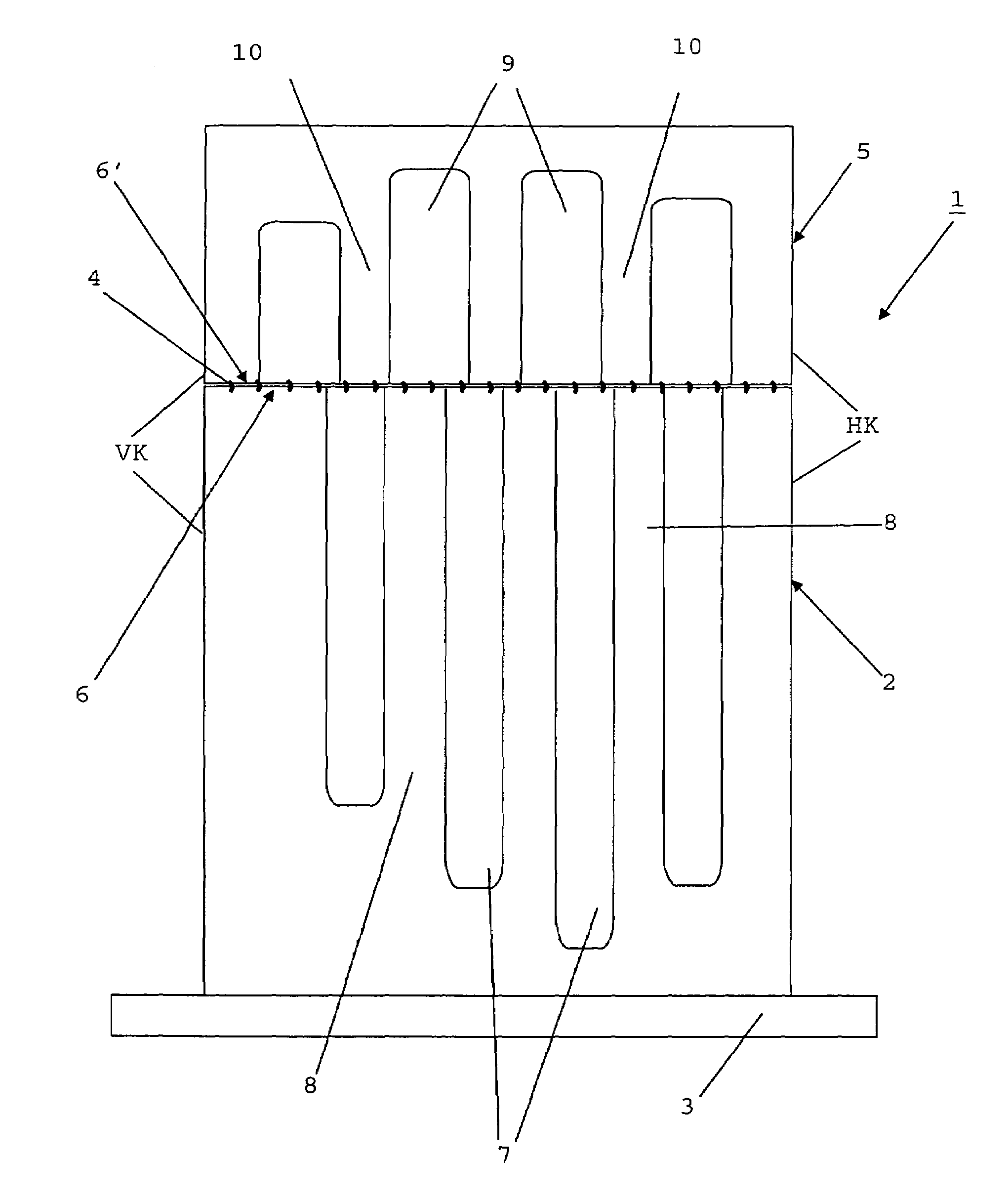
[0008]According to the present invention, the hollow fan blade is made of two blade portions, namely a blade base section and a blade tip section, assembled by a joining process, with the blade tip section being limited to the upper, low-stressed area of the hollow fan blade. The split design enables cavities to be produced over a large area of a fan blade made of solid material which, starting from the adjacent, free faying surfaces of the individual blade portions, are produced by known methods, for example electrochemical machining. The blade is split in an area in which the joint will withstand the forces acting in this area without any problems, so that the production of such a joint is possible and permissible as neither reliability nor life are affected. The added blade tip section may, however, also be made of a sheet-metal structure, which has larger cavities and, therefore, less weight than a blade tip section made of solid material, and which also can be assembled to the solid, cavitary blade base section by known joining processes, for example laser welding. The portion connected in the tip area by a joining process can be of filigree design since the operating loads are relatively low (e.g. stresses of max. 150 MPa). In the case of foreign object damage (FOD), the potential mass loss at the fan blade tip is so small that the resultant imbalance will not lead to an automatic shutdown of the engine.

Problems solved by technology

In the case of foreign object damage (FOD), the potential mass loss at the fan blade tip is so small that the resultant imbalance will not lead to an automatic shutdown of the engine.

Method used


Image

  • Hollow fan blade for aircraft engines and method for its manufacture
  • Hollow fan blade for aircraft engines and method for its manufacture
  • Hollow fan blade for aircraft engines and method for its manufacture

Examples


Embodiment Construction

[0012]According to FIGS. 1 and 2, the fan blade 1 is of a two-part design and consists of a blade base section 2 (blade bottom portion 2) with blade root 3 and a blade tip section 5 (blade top portion 5) assembled to the blade base section 2 by means of a joining weld 4. The blade base section 2 according to FIGS. 1 and 2 is made of metal, for example titanium, or a metal alloy, and contains, in its interior, several, long cavities 7 with essentially rectangular to oval or round cross-section which originate at the upper abutting edge 6 of the blade base section 2. The cavities 7 are dimensioned such that the remaining wall thickness and the thickness of the reinforcements 8 formed between the cavities 7 provide a fan blade 1 which satisfies the high load and strength requirements in this area. This applies similarly to the depth of the cavities 7, which can be larger in a mid-section than in the higher loaded outer sections near the leading edge VK or the trailing edge HK, respecti...


PUM

PropertyMeasurementUnit
weightaaaaaaaaaa
strengthaaaaaaaaaa
poweraaaaaaaaaa

Abstract

A hollow fan blade for the fan of an aircraft engine includes a blade base section (2) and a blade tip section (5) which are assembled at opposing faying surfaces (6, 6′) by a joining process. Starting from the respective faying surface, cavities (7, 9) are produced in the two blade portions (2, 5) which are dimensioned in accordance with the loads occurring in the respective blade areas. The joining weld (4) is in a low-loaded area. The blade base section and the blade tip section can be constructed of solid material with formed-in cavities. The blade tip section can also be a sheet-metal structure.

Description

[0001]This application claims priority to German Patent Application DE10349073.6 filed Oct. 14, 2003, the entirety of which is incorporated by reference herein.BACKGROUND OF THE INVENTION[0002]This invention relates to a hollow fan blade for the fan of an aircraft engine with cavities provided in the blade for weight reduction and, further, to a method for the manufacture of such a blade.[0003]The fan blades are the foremost rotating components of an aircraft engine and are, therefore, subject to considerable loads by ingested foreign bodies, such as birds, primarily in the take-off phase. In order to withstand the extremely high loads, the fan blades are made of a high-strength metal, metal alloy or fiber-reinforced polymer with metallic leading edge protection and dimensioned adequately. Such solid blades are, on the one hand, very costly due to the high amount of expensive material invested and, on the other hand, the mechanical loads arising from natural vibrations, vibration am...

Claims


Application Information

Patent Timeline
Patent Type & Authority Patents(United States)
IPC IPC(8): B21D53/78F01D5/18F04D29/32F04D29/38
CPCF01D5/147F02K3/06F04D29/324F04D29/388Y10T29/49339Y02T50/671Y02T50/673F05D2240/30Y02T50/60
Inventor SCHREIBER, KARL
Owner ROLLS ROYCE DEUT LTD & CO KG
Learn More